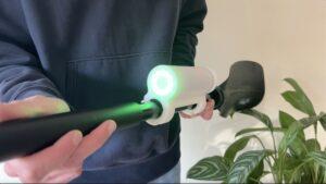
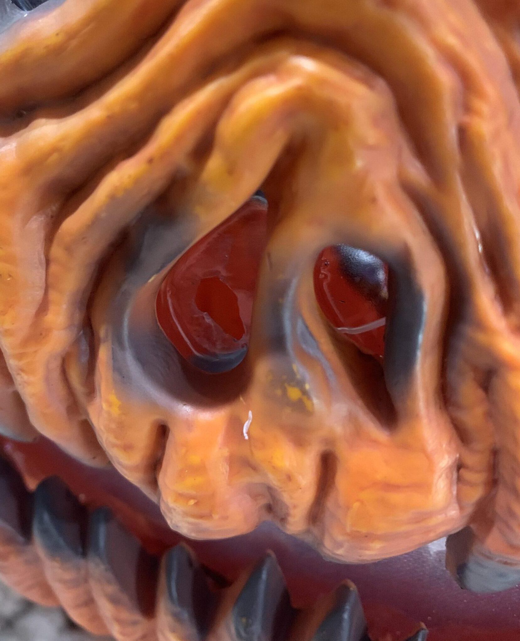
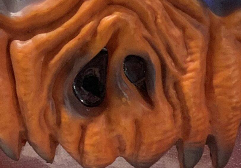
Meet Gourdan, the Jack-O-Lantern who follows tricker treaters to the door and back with his eyes.
My sister and I both married Halloween fanatics. Anything from scary movies to decorations, our spouses love everything spooky. Growing up I hated scary movies and my family never really got into the Halloween spirit. In fact I remember one Halloween my parents turned off all the lights, shut our gate and let the dogs out during peak tricker treating hours. That said, over the last few years I have grown to love the adrenaline roller coaster that is a scary movie or haunted house and thoroughly enjoy Halloween as one of my favorite holidays.

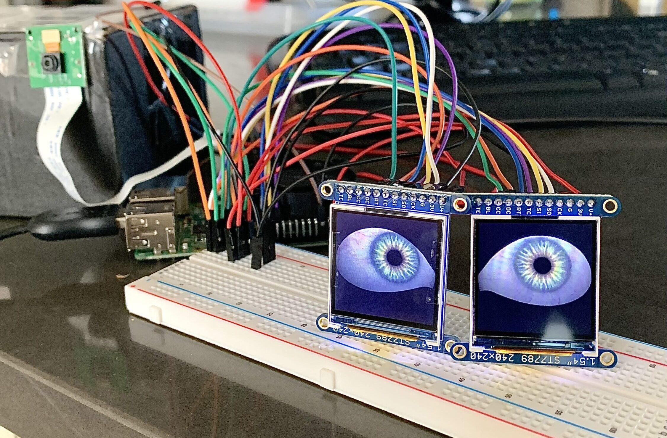
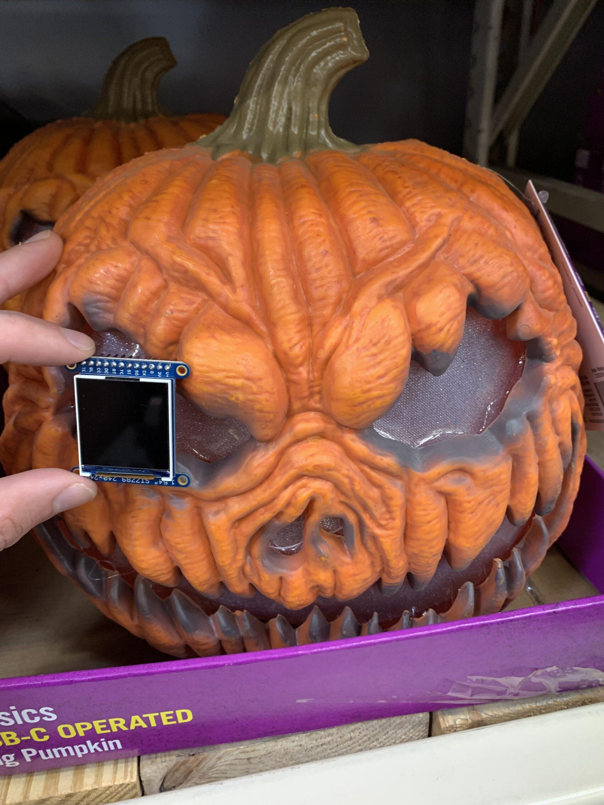
When my brother in law was a kid, he loved decorating the yard for Halloween. Since recently buying their first home, he wants to one day turn it into a Halloween attraction for people all over the city. When I heard this, the maker in me couldn’t resist getting involved. After all, Halloween is prime time for people like us, providing an excuse to spend money on new toys and tools. After scrolling for inspiration on Adafruit, I came across these LCD eyes and knew I wanted make some sort of eye following Halloween prop. And thus, Gourdan was born.
Project Overview:
Downloads:
- Software: https://github.com/BradenSunwold/imacreep
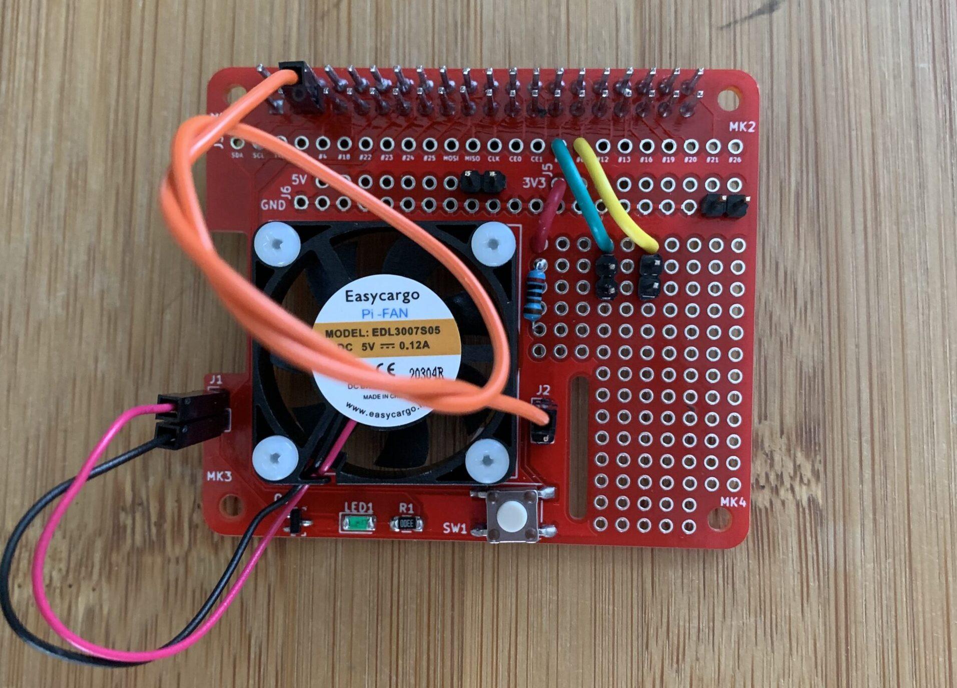
- proto-power-hat: https://barenakedembedded.com/raspberry-pi-fan-enable-circuit/
- 3D prints: https://github.com/BradenSunwold/imacreep/tree/main/3D_Prints
OpenCV:
LCD TFTs and Adafruit Drivers:
Stitching Everything Together:
Object Detection:
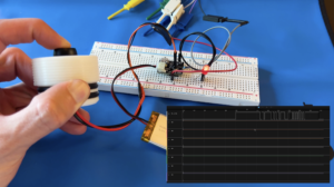
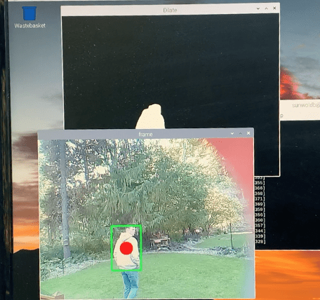
The Adafruit eye graphics only runs on a headless image. Unfortunately, this means that tuning the camera and object detection is not possible on this image. The object detection will still run but there are no display drivers to show what is happening real time in order to tune it. So I ended up using two separate SD cards with two separate images, one to test the object detection and one to run the final setup with the eyes. First, we’ll touch on the object detection / tracking image.
Configuring the Image:
sudo apt-get update
sudo apt-get upgrade
sudo apt install python3-opencv
sudo raspi-config
vcgencmd get_camera
python3 TrackerTuning.py
-
TrackerTuning.py – Allows you to only run the object tracker software without the LCDs connected so that you can tune the algorithms using the OpenCV Pi image
-
eyesTracker.py – This is the final software that will run on the eyes image. It runs the object detection and the LCD eyes
-
objectDetector.py – Runs the stable camera object detection algorithms. This grabs each object seen in the current frame and feeds it to Tracker.py
-
Tracker.py – This takes in latest object coordinates detected by objectDetector.py. It determines what is seen as a valid object and wether the tracker is looking at the same object as the previous frame or not
Tracker Tuning:
The object detection algorithms can behave differently in different environments and may have to be tuned accordingly. I have seen factors like lighting and background movement (cars, trees, etc.) effect the optimal tuning. There are various parameters that can be adjusted to achieve the best possible results. I would recommend tuning the tracker once before final integration to get familiar with the code and ensure everything runs correctly, then once again when integrated into the final product.
-
TrackerTuning.py – lines 20 – 21:
-
These lines are pre-canned OpenCV algorithms that detect a stable background. Each use a different algorithm and respond to various background environments in different ways. Comment out one or the other and try each with various input parameter till you find the best combinations.
-
-
history – Amount of frames taken into account to determine stable background. Higher will be more accurate but less sensitive to rapid movement.
-
varThreshold – Think of this parameter as sensitivity. The higher the value, the less false positives but the tracker will also be less sensitive.
-
-
-
history – Amount of frames taken into account to determine stable background. Higher will be more accurate but less sensitive to rapid movement.
-
dist2Threshold – Think of this parameter as sensitivity. The higher the value, the less false positives but the tracker will also be less sensitive.
-
-
-
TrackerTuning.py – line 45
-
This if statement determines the minimum and maximum size of a contour (white detection blob) that is considered a valid object. Sometimes the tracker sees your arm, head and body as three different objects. You’ll have to tune it to detect a large enough area so that it’s not tracking little arm movements but small enough that it isn’t throwing out valid objects. When the lighting rapidly changes in a scene, the tracker can have moments of glitching where it thinks the whole frame is moving. The maximum contour area is specified in order to ignore this glitching.
-
-
Tracker.py – line 15
-
The hysCnt variable acts as a hysteresis for deciding when an object should be tracked or not. The tracker.py needs to see the same object a total number of hysCnt + 1 times (default 3) before it is considered a valid object. It also needs to see a valid object lose tracking a total number of hystCnt + 1 times (default 3) before considering the object out of frame. Increasing this value will improve the chances that a real object is being detected but will also make the tracker less sensitive.
-
- Tracker.py – line 34
- This if statement determines if the latest object fed from the objectDetector.py is the same object as the previous frame. It checks if the new object is less than the given amount of pixels away from the previous object. Increasing this value will make the tracker less sensitive to intermittent dropouts but more sensitive to false tracking.
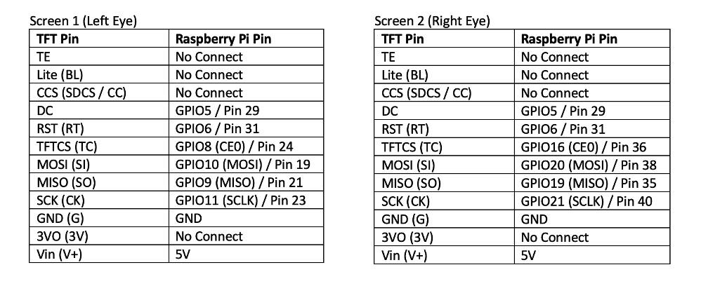
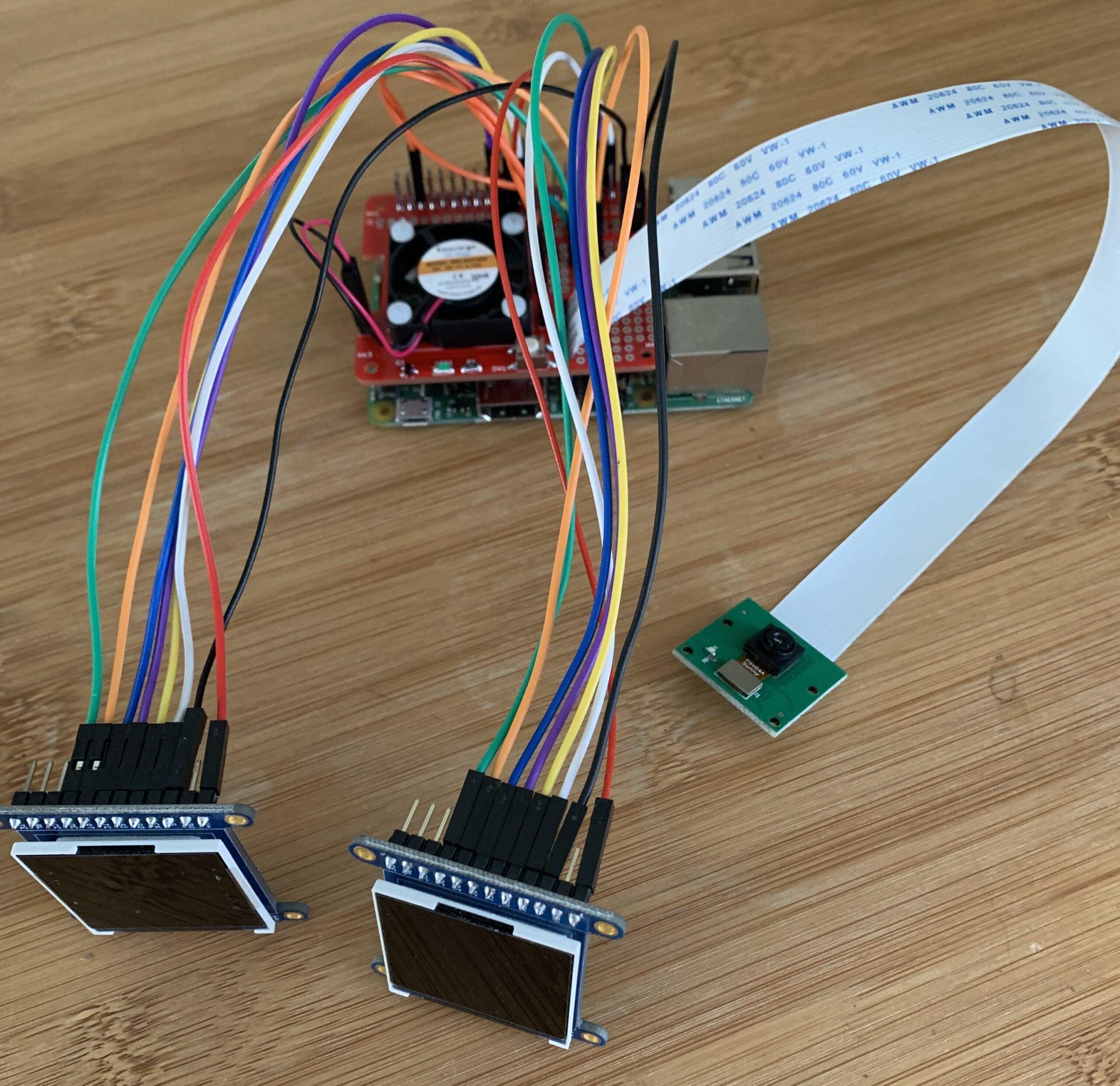
LCDs:
Now set up and connect the LCD eyes. Use another SD card for the image that will drive the LCDs and eventually, the final integrated project. Adafruit has some helpful tutorials that we will rely on for the initial setup.
LCD Image:
Follow this Adafruit tutorial in order to setup the second pi image used for the LCDs. To start with, use Pi Imager to burn the Legacy Lite OS and ensure to pre-load your WIFI password. After burning the image, the IP address of the pi should print out on startup. You can hook up an HDMI monitor and keyboard or SSH into the pi for the remaining setup and work. If SSH-ing into the pi, it can be helpful to set a static IP address so it does not change on you in the future.
Continue following the Adafruit tutorial and run the eyes installation scripts. If you plan on using the barenakedembedded proto-power-hat then do not select the GPIO orderly shutdown option. Also select no for ADC support. If you get an error message stating that this OS needs to be installed on the headless Legacy 32 bit OS, double check that you installed the correct version and if so then just ignore this warning. I got this warning message even when installing on the right OS.
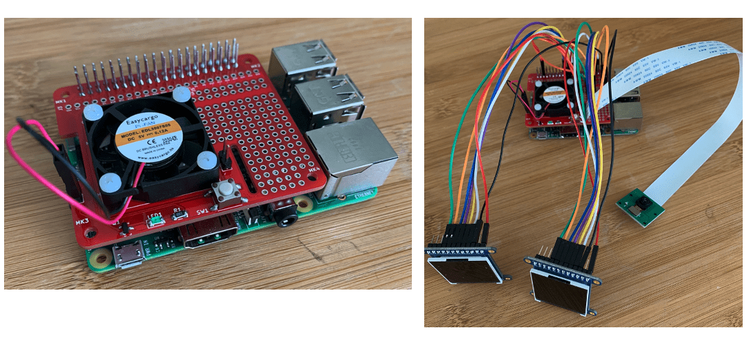
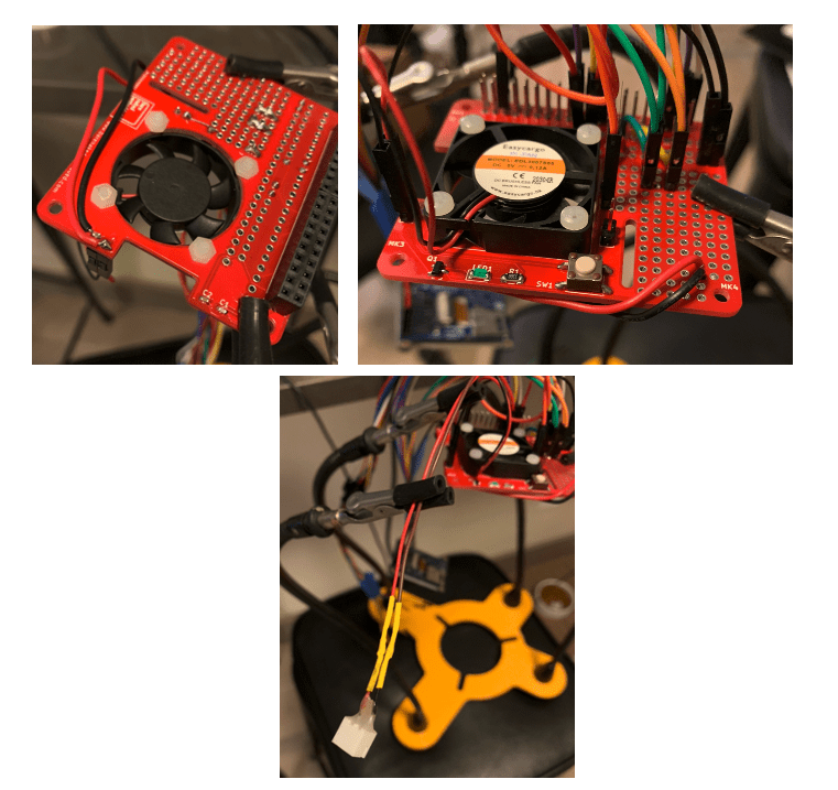
LCD Connection and proto-power-hat:
Custom Code Setup:
-
Python3 eyesTracker.py –radius 240
- eyesTracker.py – line 381
- This scales the tracked objects Y coordinates from the 640 X 480 camera resolution to the LCD 60 X 60 resolution. Since we are mostly concerned with the X movement, the default Y resolution scaling is set to half of the LCD resolution (30). This way the eyes don’t look too far up or down. Edit this scaling if you want more or less Y eye movement
- eyesTracker.py – lines 383 – 389
- This section helps to exaggerate the X movement by increasing the final X position of the eye based off the tracked object position. The default is 3 but can be increased or decreased if the eye position does not appear to line up with the tracked object in real life.
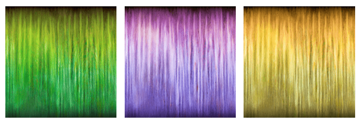
- Eye color – line 114
- Edit “graphics/iris.jpg” to whichever preferred iris color within the imacreep/graphics folder
- Eye whites – line 116
- Edit “graphics/sclera.png” to whichever preferred sclera within the imacreep/graphics folder
Integration:
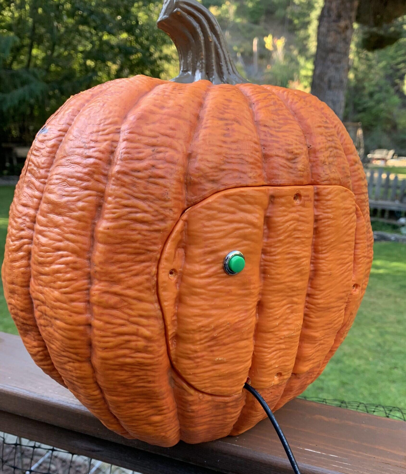
With the electronics portion of the project finished, it’s time to find a suitable home for your eye following Halloween prop. After tossing around ideas from plastic skulls to movie masks, I decided to use this light up Jack-O-Latern from Home Depot. Obviously these next steps will differ based on what you choose to mount the eyes in but I will still outline my process and any tips I learned along the way. The eyes are pretty close to the size of an actual human eye so keep that scaling in mind when picking a prop. I also highly recommend picking something where you have access to the back / inside for ease of mounting.
Prepping the Pumpkin:
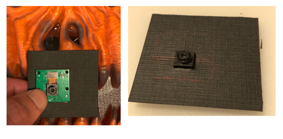
The jack-o-latern I chose had a clear plastic molding that laced the inside with a shimmery film glued over the eyes, nose and mouth to reflect the LED strip in the back. To start with, I carefully removed the shiny film over the eyes and nose for LCD and camera mounting. After some testing, I decided to place the camera in the nose as it would be the most concealed and easiest to mount. I cut a tiny hole in the plastic molding for the camera but left the plastic in tact over the eyes to help keep moisture away from the LCDs. I decided to black out around the LCD eyes and nose so that the LED strip would only illuminate the smile and the screens / camera would stay hidden. To achieve this, I used construction paper and an obscene amount of hot glue.

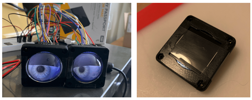
I modified some STL files from another Adafruit project that mounted these eyes into a skull. I was originally going to use some glass lenses over the eyes to create a rounded effect but ultimately thought it looked best without them. Both the lensed and non-lensed versions of the 3D prints can be found in the imacreep repository, in the 3D_Prints directory. There are three versions of the 3D prints, one for a plastic lens with no lip, one for a glass lens with a lip and another for no lens at all. Refer to the LCD files, not the OLED.
Time to Hot Glue:
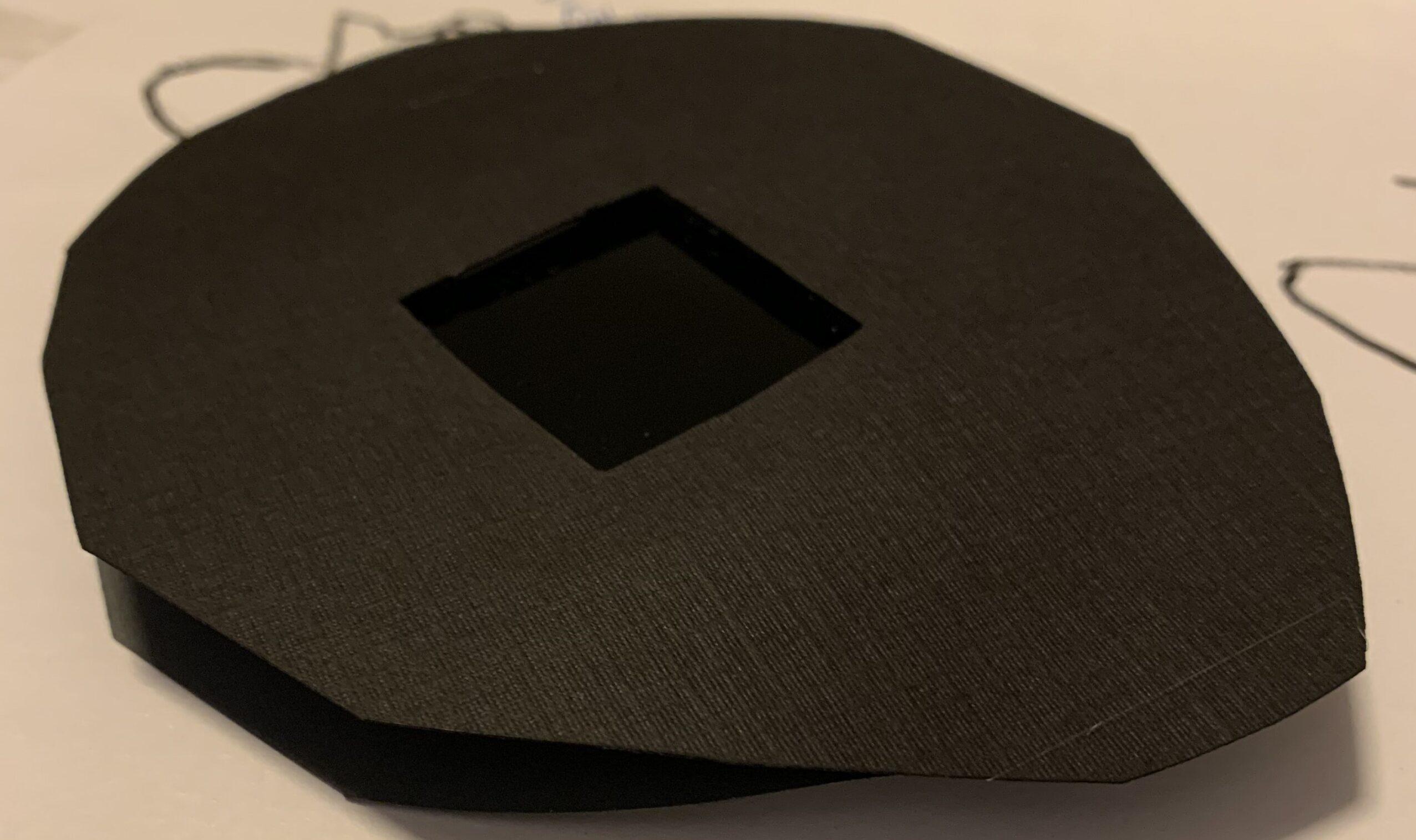
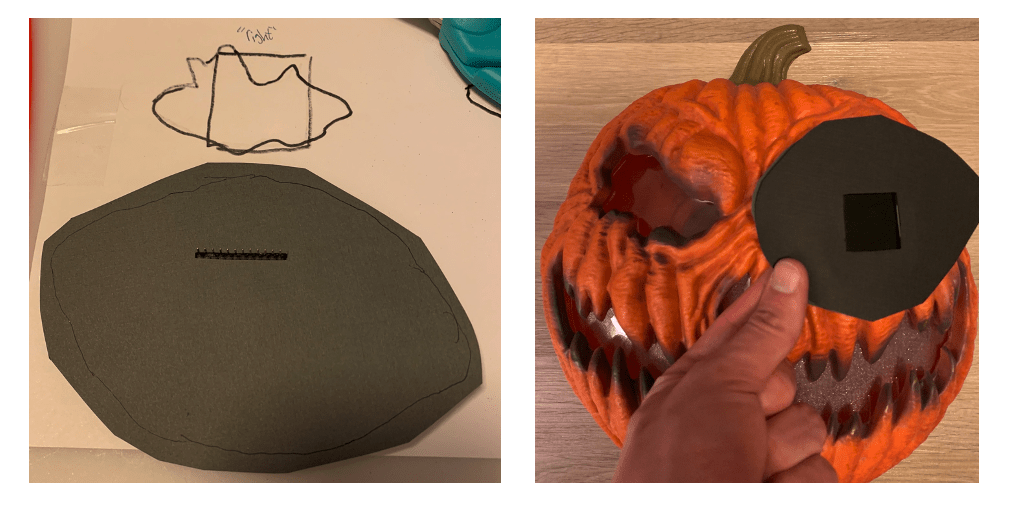
I decided to sandwich the LCD screen between pieces of construction paper with hot glue in order to get a strong hold. It also allowed me to curve the top layer to match the curvature of the pumpkin.
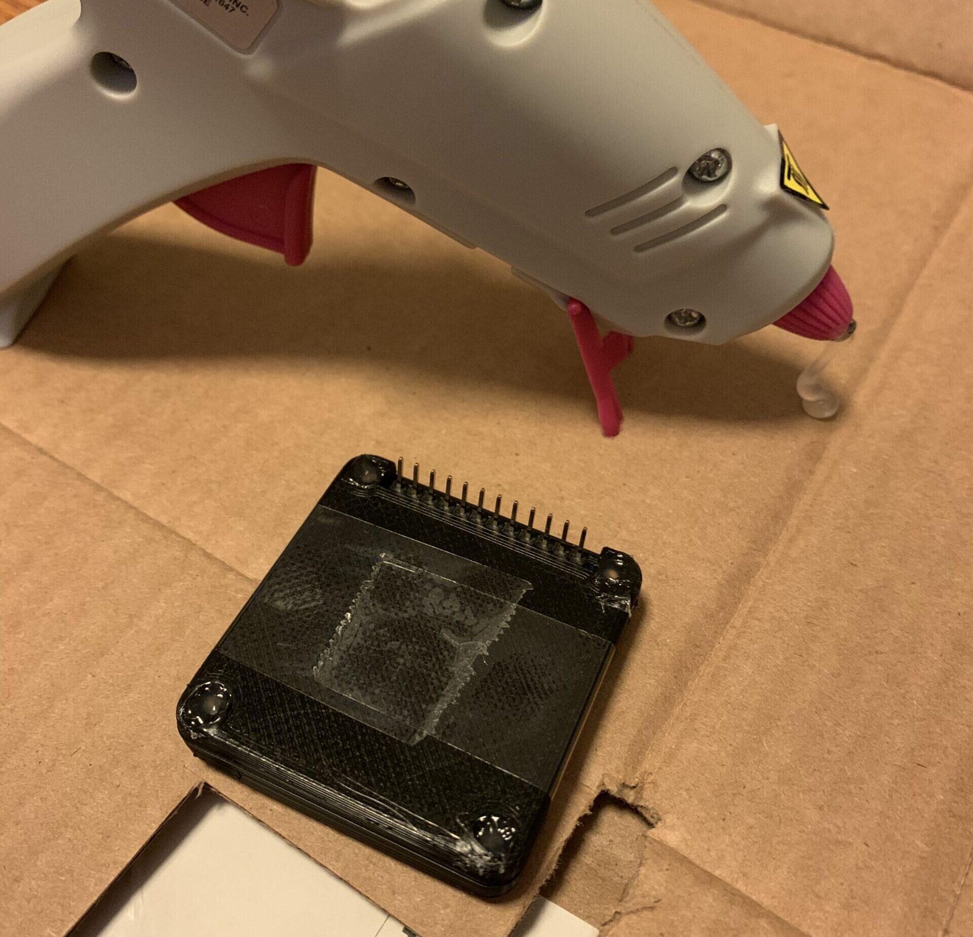
First assemble the LCDs into the 3D prints. Each case takes four #2-56 flat head machine screws, 3/8″ long, plug matching nuts. But I was on a time crunch and all the hardware stores around me were closed so… you guessed it, more hot glue! I placed an LCD into the case then taped it together temporarily in order to fill in each screw terminal with hot glue. Once the glue set I placed more glue around the middle where the two halves joined.
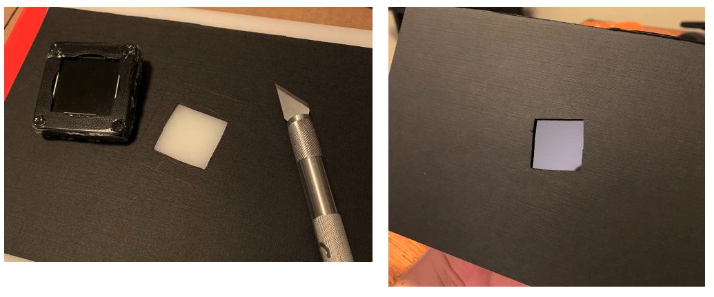
Next, cut two pieces of construction paper in half that will act as our clam shell. Take the other empty case and trace out an outline of the outer case and inner screen cutout. Use an exact0-knife to cutout a hole for the screen. Hot glue the case onto the construction paper so the screen lines up with the cutout that was just made.
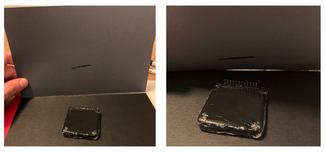
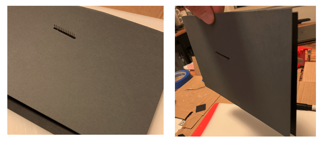
Now to create the clamshell, line up the other half of construction paper and start to fold it down till it touches the header pins of the LCD. Use a sharpie draw a rough line where the header pins meet the paper. cut a small slit, the length of this line for the pins.
Glue the second sheet to the back of the case so the LCD is sandwiched between the two pieces of paper.
Now create a rough outline of the eye shape and start cutting down the construction paper. Start by leaving more excess than needed, you can always cut away more. Be sure to keep in mind the position of the LCD screen. We want the LCDs evenly spaced, fairly vertical and in a section of the pumpkin eyes where they won’t be cutoff. It helped me to trace the pumpkin eye holes and draw out where to place the LCD.
After you get the sizing right, glue the left and right edges together to create a slightly rounded effect.
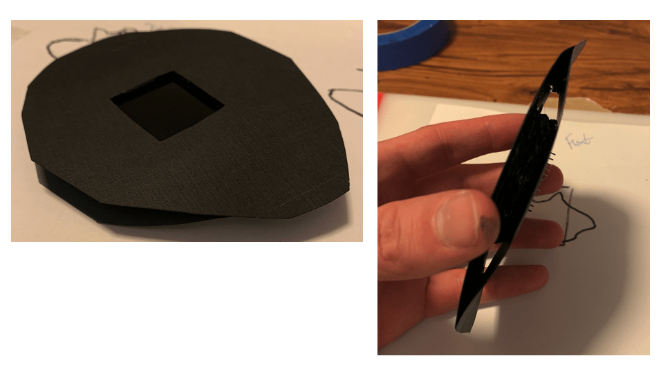
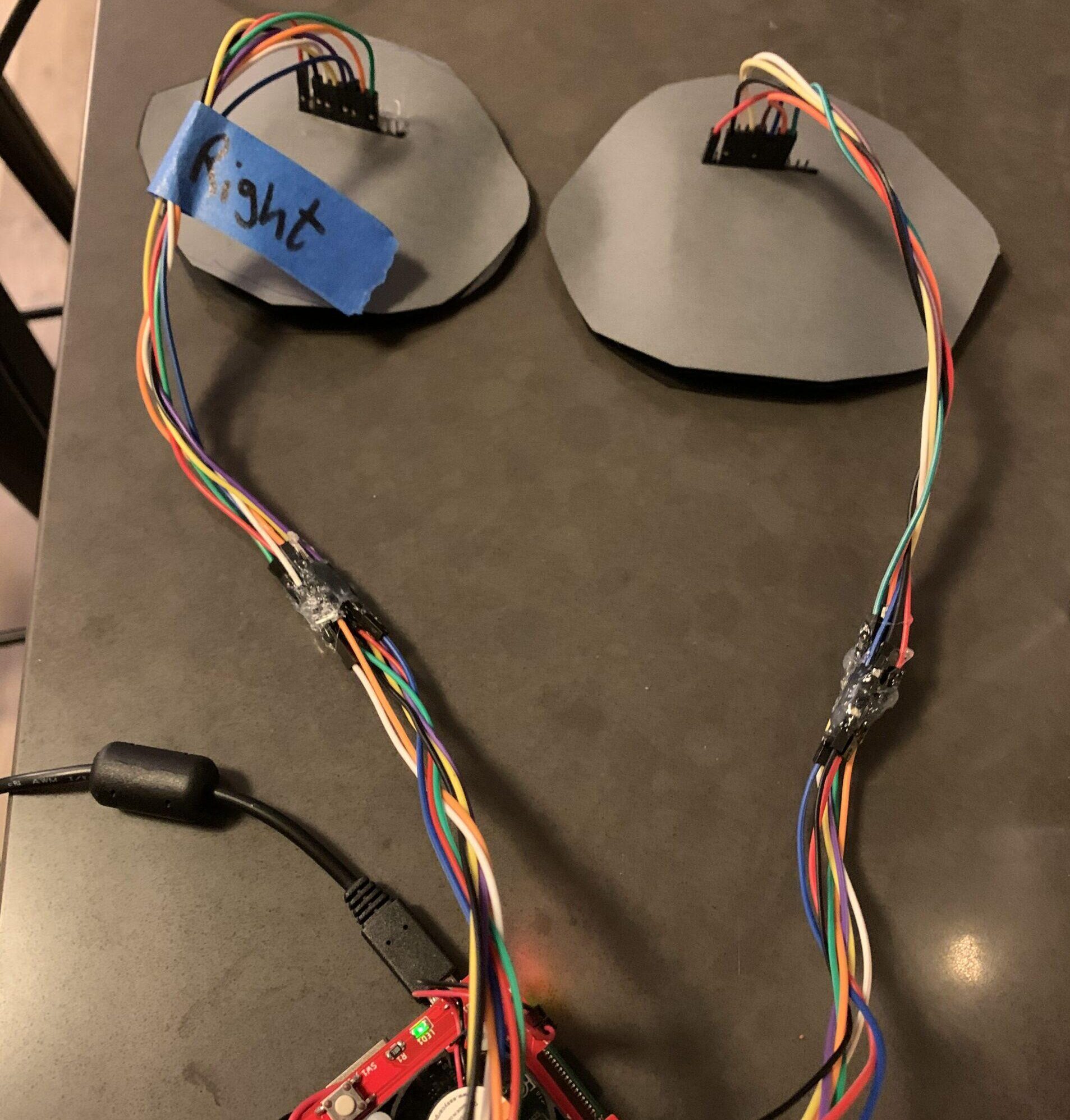
Repeat the same steps for the other eye. Make sure that your paper clamshell is small enough to fit through the back opening of the pumpkin and doesn’t overlap too much onto the other eye clamshell. Once both eyes are finished, it’s helpful to label one right of left to keep track when completing final mounting. I also added another jumper wire to each LCD signal to give myself more slack for mounting. Since I don’t intent on ever taking this thing apart, I hot glued all the jumper wire connections.
More Hot Glue:
Now that the eyes are ready for mounting, it’s time to get the camera ready to mount into the nose. Measure out a square that will cover both nose holes and cut it out of the black construction paper.
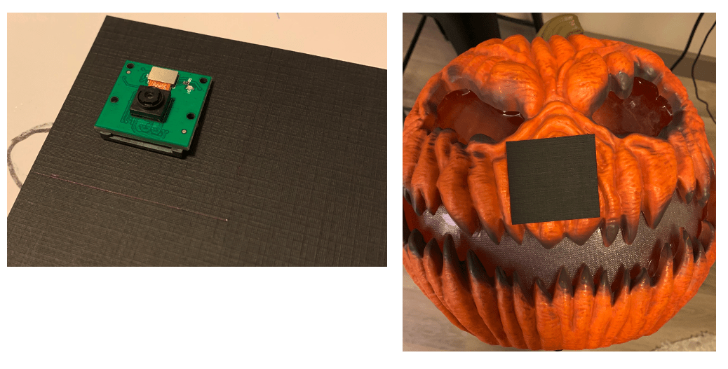
Align the camera module with the right nose hole and mark it on the construction paper. Cut out a square the size of the actual camera and glue the camera module down to the construction paper.
The camera and both eyes should be ready to mount into the pumpkin but first let’s make a few mods to the LED circuit that came with the pumpkin and add an external power button.
Final Mods:
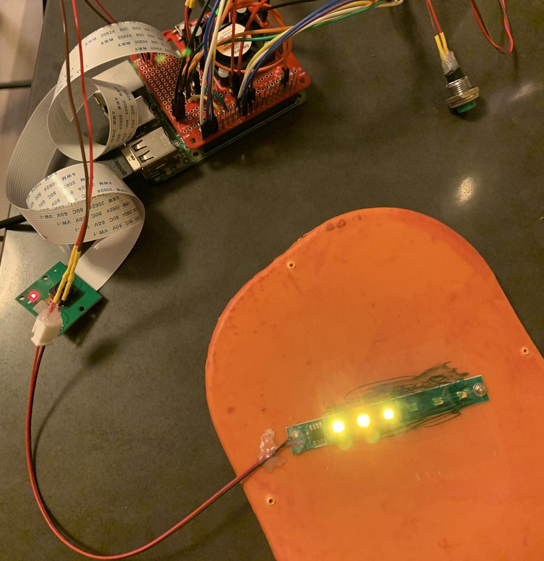
The pumpkin came with an LED strip screwed to the back cover that connected to a battery terminal in the bottom. Since it ran off 3 AA batteries (~4.5V), I figured that I would be able to run the LED strip from either the 3.3V or 5V pin off the raspberry pi. I clipped the connector wires coming from the battery terminal and soldered them to the 5V fan enable circuit on the proto-power-hat. That way, the LED strip would turn on and off with the Pi.
The LEDs powered off 5V fine but were a little too bright. I placed a piece of clear packing tape over the LEDs and colored them in slightly with a green sharpie to match the green eye color but also to dim them a bit.
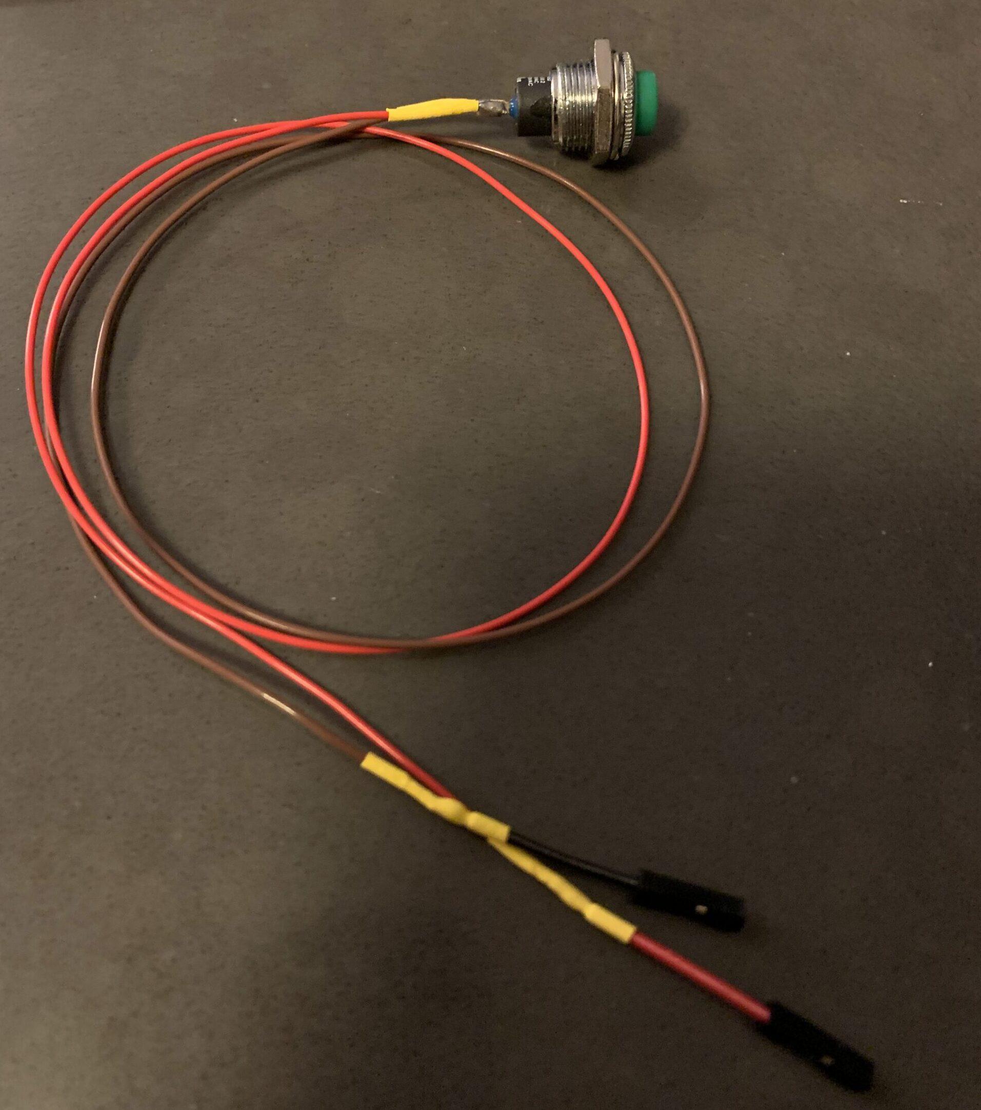
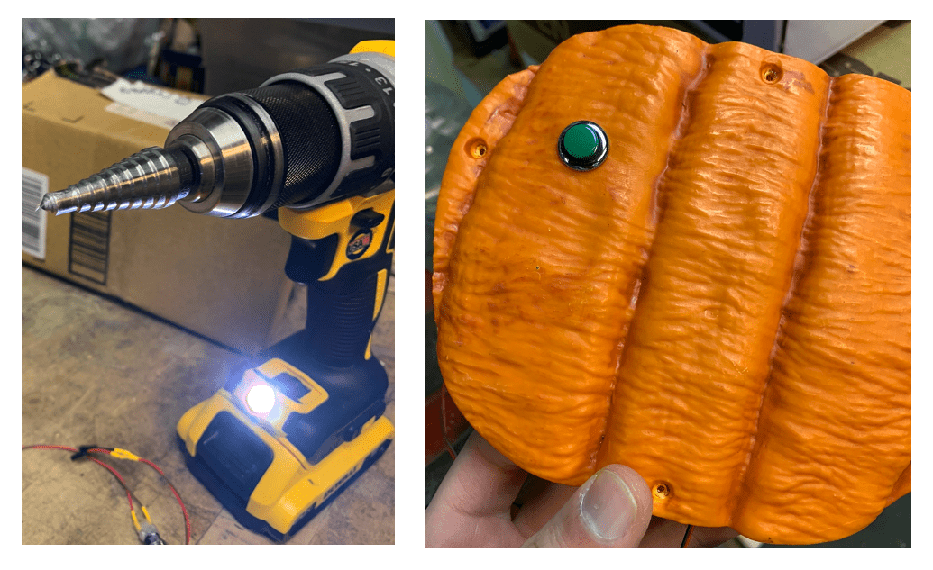
I wanted an on/off button accessible on the outside of the pumpkin so I mounted a push button into the back of the pumpkin. First, solder female jumpers to the pushbutton and connect them to the proto-power-hat external button header.
The back of the pumpkin is hollowed so use a hole saw bit to drive through the inner layer giving you enough room to mount the button.
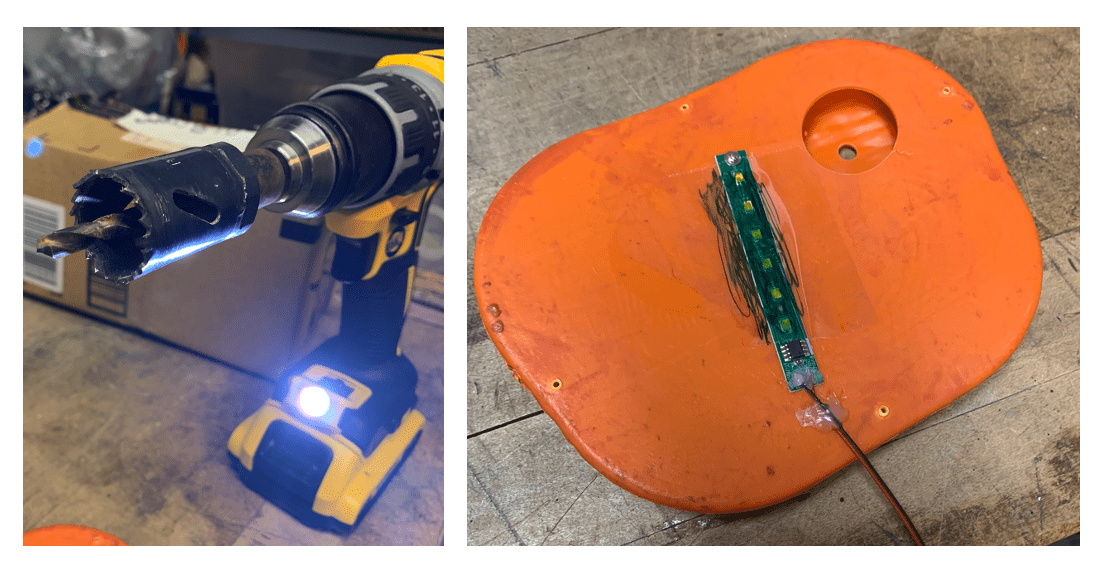
Use a stepped drill bit to cut a hole into the outer layer fo the pumpkin where the inner layer was just cut. Keep incrementing the hole size until the button cleanly fits into the hole, then screw on the nut.
The last mod that’s needed is a hole for the Pi power chord. Use a regular drill bit that is larger than the power chord diameter and cut a hold as close to the bottom of the pumpkin as possible. Then use an exacto-knife to cut off the edges.
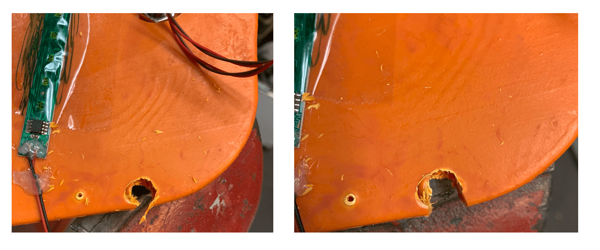
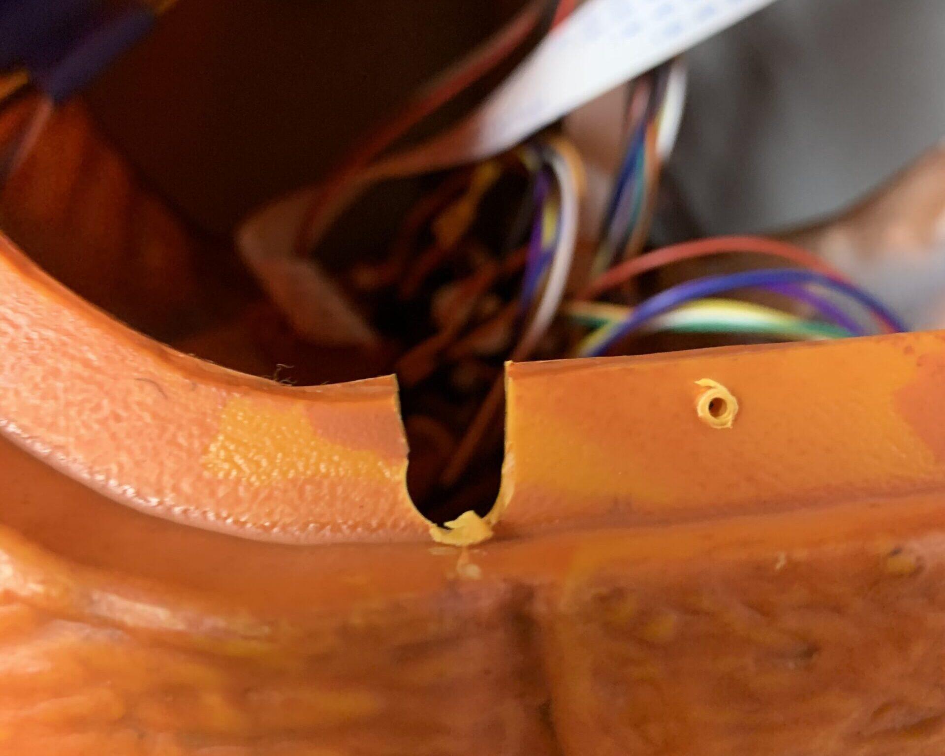
The pumpkin has a plastic lip that the back sits on and screws into. Line up the hole that was just cut and use an exact0-knife to cut away the plastic lip to make room for the power chord to feed all the way through.
With that last mod, it’s time for the final assembly!
Mounting:
It’s helpful to have an extra pair of hands for this part. Mounting the eyes is a bit nerve wracking but sooner or later you just have to put your faith in the hot glue. I placed glue dots on corners of the interior plastic (circled in green) so they would help hold the construction paper clamshell but not be visible.
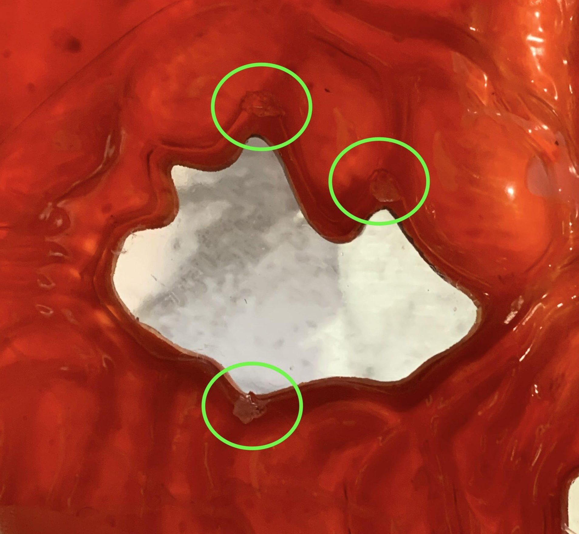
With the glue dots in place, I quickly spread hot glue all along the most outside of the construction paper clamshell and stuck it to the plastic interior. I had someone watch my placement from the front and tell me how to adjust the eye positioning before the glue dried.

For the camera, I decided to cut out a small hole in the nose plastic. Although this defeats some of the weather proofing, I thought the plastic might fog up over the lens and ruin visibility. I highly recommend you turn on the Pi using the OpenCV test image with a monitor connected when mounting the camera. The nose hole is so small you have to perfectly align the camera in the center to avoid blocking part of the field of view. With the camera running, mark the best placement of the camera in the nose with a sharpie. Use an exacto-knife to cut out a small circle around the sharpie mark.
Using the same glue dot / hot glue technique as for the eyes, mount the camera into the nose. Again, I recommend having the camera running while mounting to ensure proper placement.
Wrapping Up:
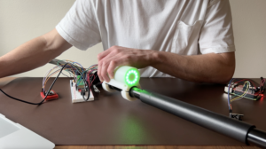
With everything mounted, we’re ready for final testing! Place the pumpkin where it will be displayed and turn on the Pi using the OpenCV test image. complete the final object detection tuning from this position and copy over the optimal tuning parameters to the LCD image. Power up the LCD eyes image and get ready to spook the neighborhood kids! At this point, turn on the auto-startup as described in the Custom Code Setup section and place the Pi inside the pumpkin.
Last, all the wires and camera ribbon cable will cast shadows onto the smile so do your best to move the cables out of the way. Consider removing the LED strip from the back of the pumpkin and placing it on the bottom of the pumpkin to avoid these shadows.
Going Forward:
I think there are some great opportunities to expand on this project for next year! Some thoughts I have had are enabling a random eye movement if no one has been detected after a given amount of time so that the eyes aren’t just stuck in one position until the next person walks by. I also want to try and play around with different expressions. I think it would be really interesting to detect how close someone is and change expressions accordingly or set up some sort of jump scare.
As always, hope you enjoyed and thanks for reading! Leave a comment if you make your own eye following Halloween prop or have ideas to make it better!
If you found this content interesting or useful, buy me a coffee!
Bitcoin Wallet:
bc1q0vkx34w5y4yt5nq38a4rvk7gvgnxm2xv5lvyft