
I’ve always loved the water. I was a life guard, work on UUVs (Unmanned Under Water Vehicles) as a career and I’m Norwegian. Living in Seattle, being surrounded by so much water, I’ve wanted to build my own electric kayak for a long time! I have also wanted to do a project involving machine learning (ML) on the edge. So I decided to combine these two ideas! This post is all about phase one of my DIY electric kayak build. Phase one of the project is all about creating the minimum viable product and proof of concept. Showing I can build an electric kayak capable of traveling a walking pace with at least a two hour range.
Check out my Part One YouTube Video to see the kayak in action!
And my full range test!
Vision
Like I said in the intro, I’ve been wanting to get my hands dirty with some edge ML. Edge ML runs on resource constrained hardware like microcontrollers or single board computers. It runs locally so doesn’t have any connection to a central server. I wanted to figure out a more unique application that was simple enough to train myself. I want to get deeper than pre-canned libraries for computer vision or language models. And frankly, don’t have the time or resources to dig down into training those type of huge models.
Edge Machine Learning
So I’m setting out to build the e-bike of kayaks! The idea is simple. Like an e-bike, the DIY electric kayak will detect when the user starts to paddle and automatically assist with the electric motor. Now on an e-bike, steering is completely removed from the propulsion system. All the bike has to do is detect when the user is peddling and turn on the motor. But with kayaking, paddling is not only used for propulsion but also to steer. Paddling is even used to keep the thing straight (at least the cheap kayaks that I use). This is where ML comes in. I am going to use sensors placed on the oars along with GPS data on the kayak to feed a ML model. This model will be able to deceiver the user’s intentions (ie: go straight, turn left or turn right). It’ll then automatically assist by turning the fin in the right direction (hopefully).
Phase one
But I’m getting ahead of myself. This article is all about phase one of the project which is creating the proof of concept. Fancy AI / ML will have to wait. For now, I needed to prove that I can build an electric kayak for a reasonable price. My goal for this first phase was to have a runtime of at least 2 hours, moving at a walking pace of 3 – 5 mph (4.8 – 8 kph). That would give a total range of 6 – 10 miles (9.6 – 16 Km). Well let’s get to the actual build! We’ll be talking all about motors, batteries and bathtubs.
Motor
The first thing I bought was the actual motor. It’s a fully waterproof e-foil motor from Flipsky that cost about $90. The motor is rated at 160kV, 500W and is a Brushless DC motor. Brushless DC motors are perfect for this application due to their high efficiency, longevity and size. They can pack a ton of torque in a very small package. They’re often used in electric skateboards, hoverboards and even some electric vehicles. This particular motor can produce 5 Kg (11 lbs) of thrust.
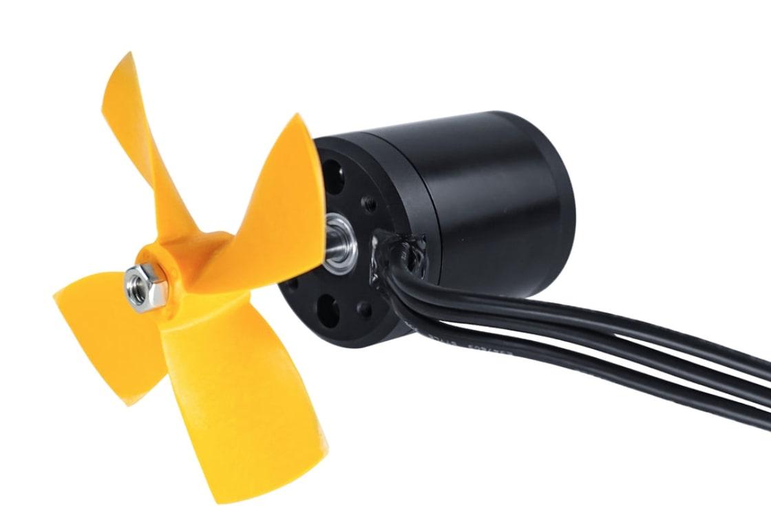
Doing some research on trolling motors, Minn Kota Trolling Motors recommended 2 lbs of thrust for every 100 lbs of cargo. I wanted this thing to be able to carry two people or a weight of about 400 lbs. That would mean a desired motor thrust of about 8 lbs. So this motor is well within my range. The propeller came with the motor but I’m sure there are a lot of design considerations that are going to affect performance.
Motor Controller
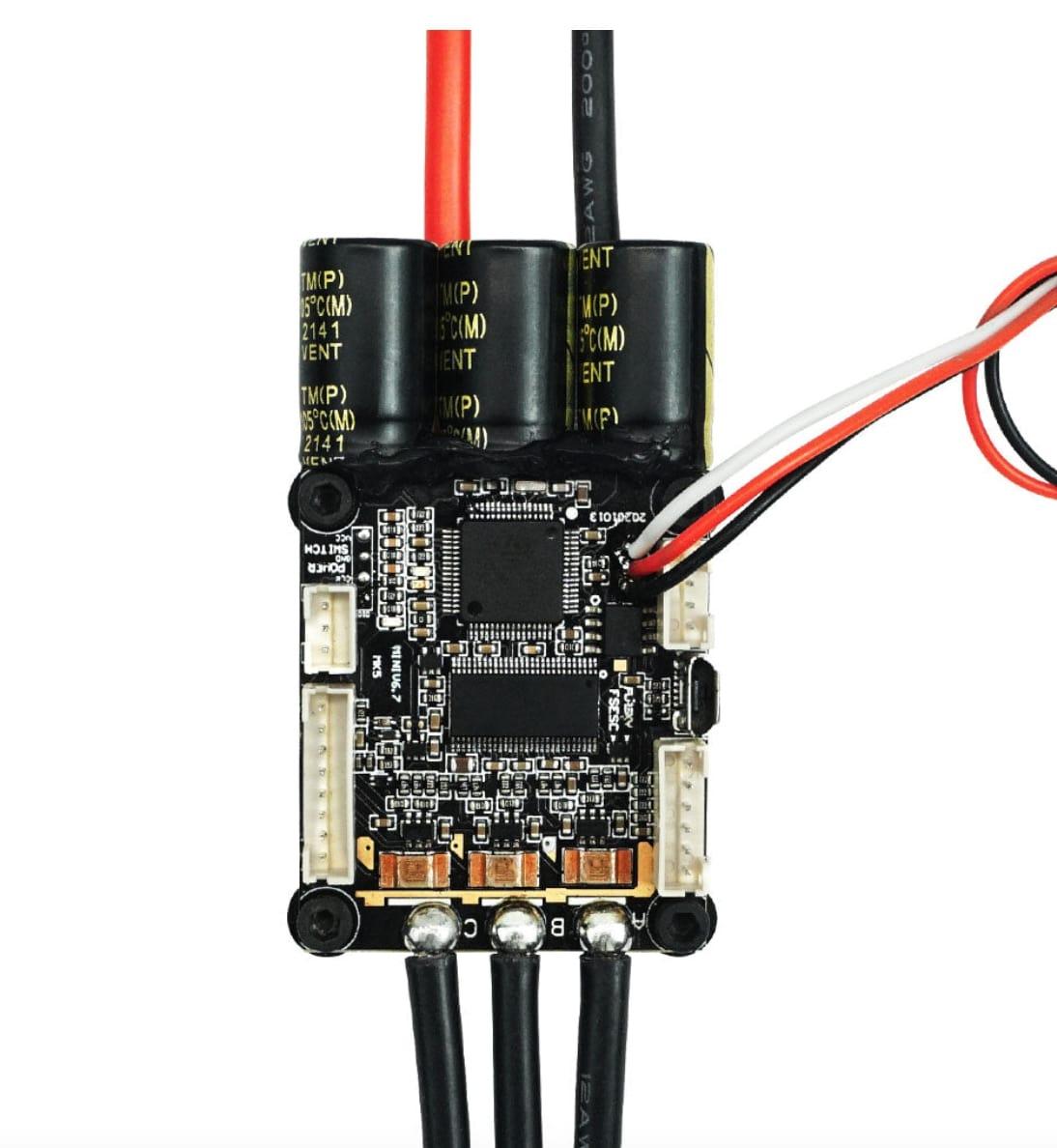
The disadvantage of a BLDC motor is the need for a complex motor controller. Unlike a brushed DC motor, you cannot apply a straight voltage to the motor and get it to spin. An H bridge circuit is needed to switch on different magnetic phases of the motor which keep pulling the rotor along. This is due to the construction of the motor phase windings. I also bought the controller from Flipsky. It’s based on an open source project called VESC that’s popular in the DIY e-skate community. While my rated motor current is 12A, the max motor current is 30A. Coming from China, I wanted a controller with a current rating at least twice my max. My controller is rated for 70A and it cost ~$80.
Fin
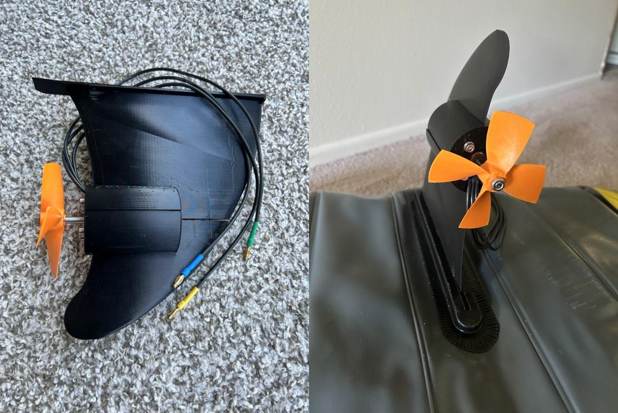
I have an inflatable Intex Explorer Kayak with an attachable fin. This Youtube video showed me how to model surf board fins in Fusion 360. I designed a new fin that would utilize the same mount but allow me to attach my motor. At first I made the fin too curved and it would have hit my propellers. After a few different iterations, I finally got something workable.
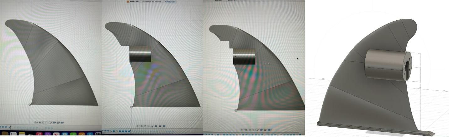
After a quick fit check, I applied some XTC-3D waterproof coating to protect the fin from the elements.
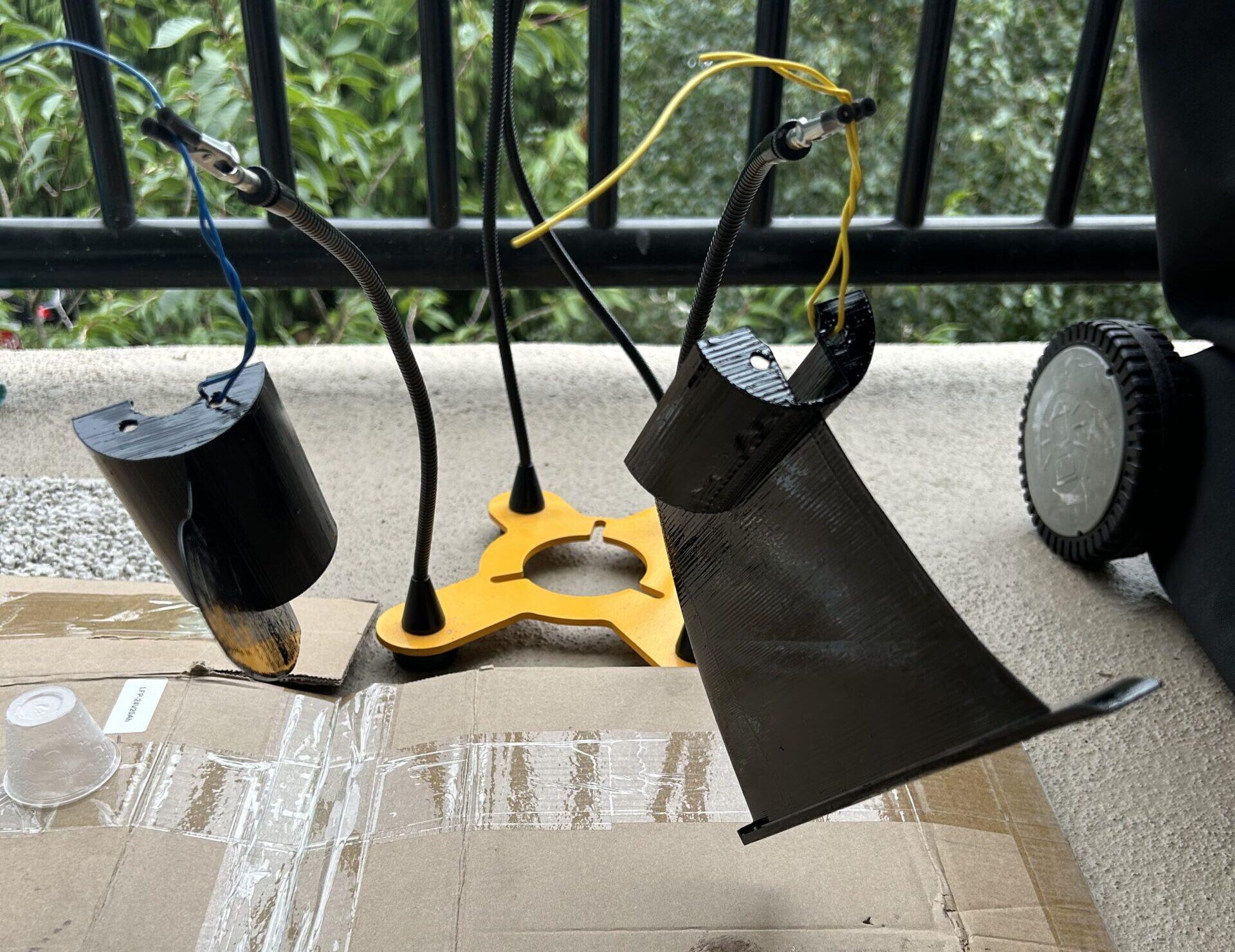
I had a few worries going into testing. I thought the fin might slide right out of the mounting slot once the motor was fully on and was worried about wobble. The motor sits at the end of the fin creating a large moment. The biggest worry was that it might wobble out of control and the prop hit the kayak hull. Luckily, during my testing, I never had either of these issues occur! I still might add some catamaran like arms to better support the fin base.
Battery
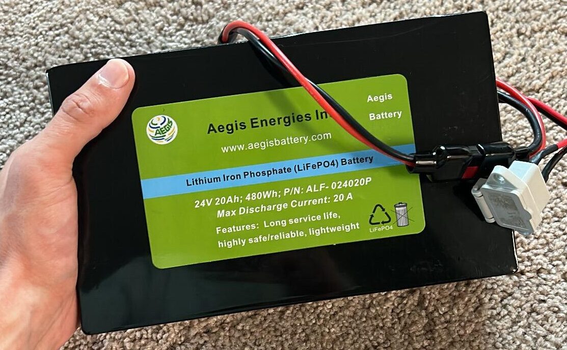
Not only was the battery the most expensive part of the design but I also had to buy two. The first one was stolen from my mail room. But that could be another blog entirely… This battery is from Aegis and luckily they gave me a half off discount on the second one. All said and done, I spent $500 on the two batteries and charger. This thing is a beast. It’s a 480W battery speced at 24V, 20Ah. That means it could power your iPhone for 6 months straight. The battery chemistry is Lithium Iron Phosphate (LiFePo4) which is one of the safer Lithium chemistries. It’s less prone to thermal runaway but still packs a punch with a high energy density. The battery weight is critical for this design. This battery is pretty heavy weighing in at 10 pounds (4.54 Kg) but hasn’t been an issue so far.
Choosing the right battery for your project is one of the most important steps! Are you curious about how to size a battery or what battery chemistry to pick? Do you have a vague understanding of energy density vs power density? Go check out my other post, How to Choose the Right Battery for your Project!
Sizing Battery
I chose this battery because I wanted my kayak to have a minimum runtime of about two hours. The motor rating is 12A at 24V. Since my battery is 20Ah, I thought this would give me a runtime of about 1.666 hours at full power. 20Ah / 12A = 1.666 hours.
But as we’ll see, after testing the kayak, I realized I miscalculated and ended up with a range of about 3.8 hours!!
Anti-Spark Switch
The VESC motor controller has big capacitors on it to handle large surges of current to the motor. Because of this, if you connect it straight to a battery, you’ll get a big spark. The battery provides a rapid change of voltage across the caps and current surges in, charging them up. This can wear out connectors and cause issues in the long term.
Circuit
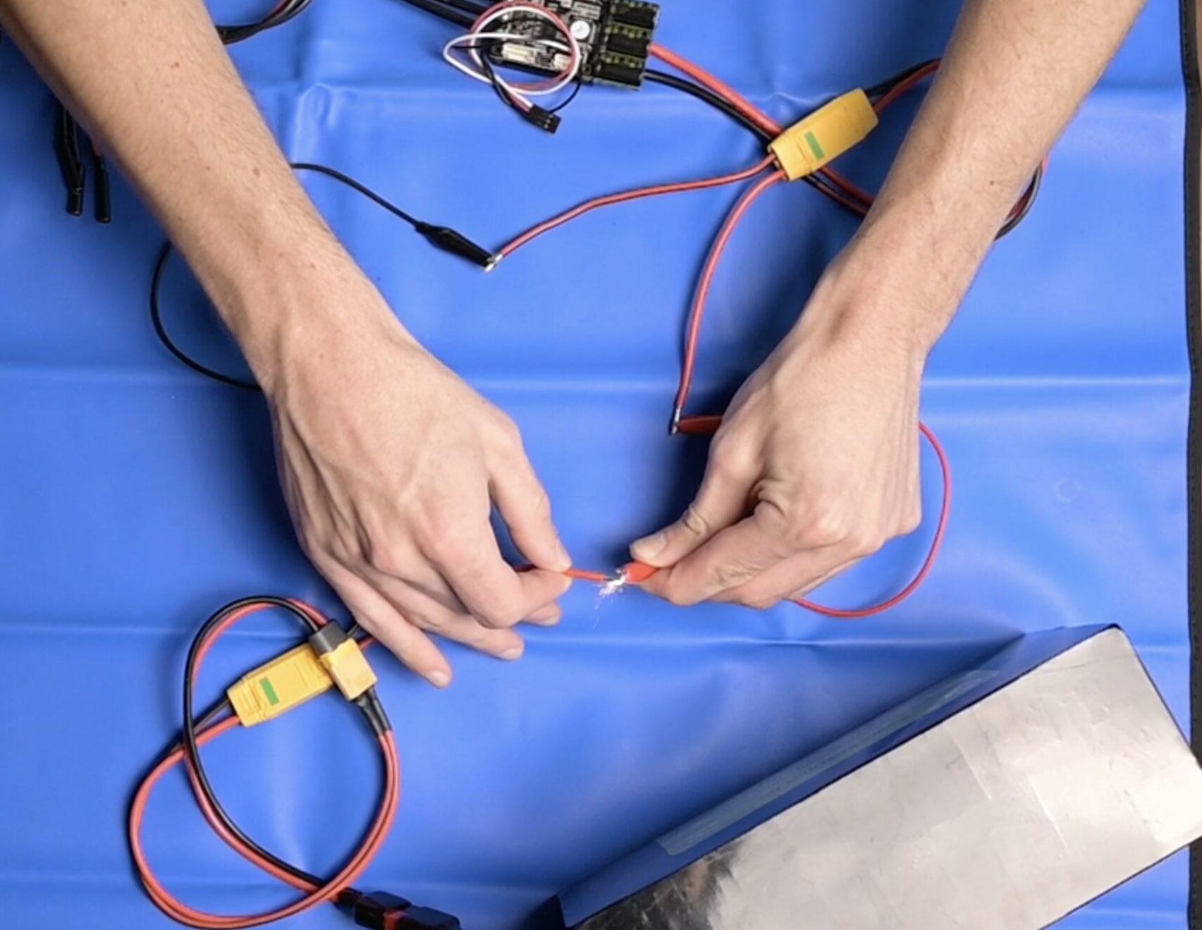
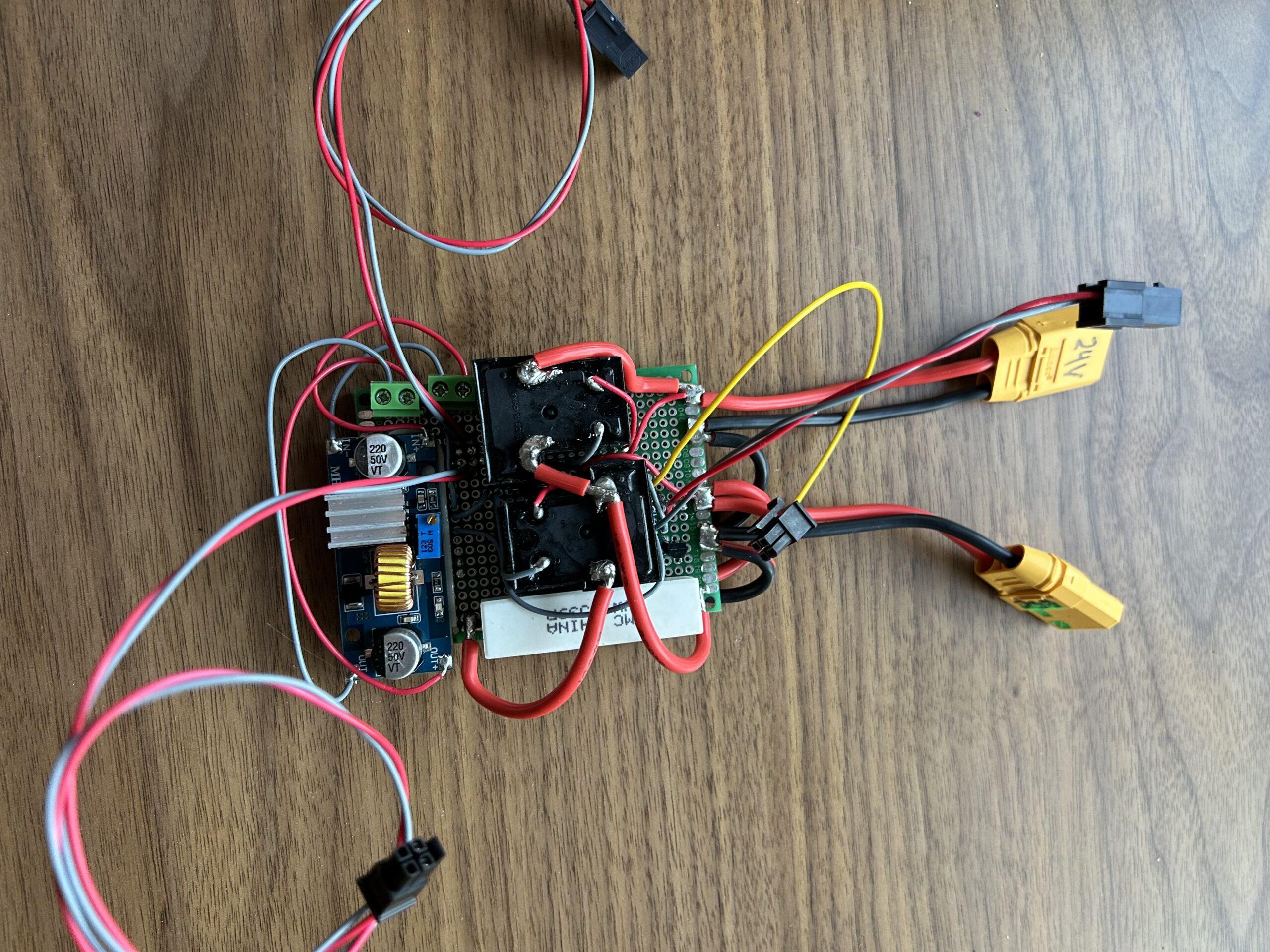
While you can buy anti-spark switches from sites like Flipsky, they’re around $40 – $80. After my battery fiasco I had already broke the budget so decided to design my own. I referenced this DIY anti-spark instructable and made a few improvements! It costs me about $8 and a couple hours of my time.
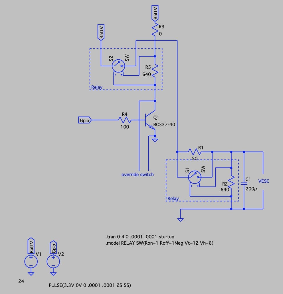
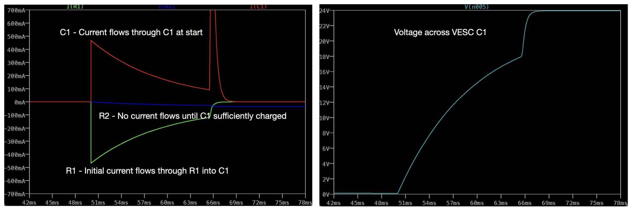
In other words, current through a capacitor is proportional to the change in voltage across it. If the voltage across the cap is constant, no current will flow. The override switch or BJT actiaves the circuit. This turns on the first relay which allows current to flow to the second circuit stage. C1 will see a rapid change in voltage across it and a limited Current will flow into it, controlled by the value of R1. Due to the rapid change in voltage across C1, it will act as a short circuit for a brief period of time. Once C1 is charged, voltage across it will stabilize and it’ll begin to act like an open circuit. This allows current to flow through the relay coil modeled as R2. The second relay turns on and allows full current to C1 / the VESC controller. In this way, the circuit soft starts the VESC, allowing the caps to pre charge which prevents any sparking.
Using the two relay stages allowed me to use a microcontroller or low current switch to turn the circuit on or off. That way I can turn on the VESC with either the Raspberry Pi or a physical switch. The relays I chose can handle up to 40A.
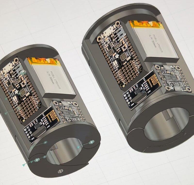
Case
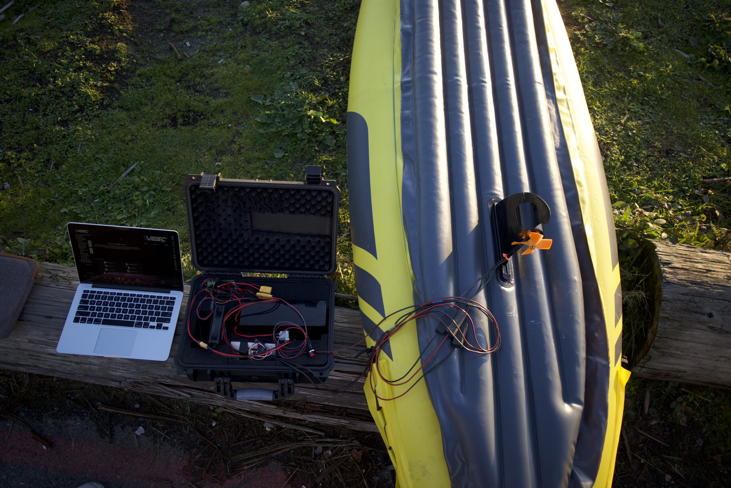
To tie everything together and water proof all the electronics, I got a cheap pelican case knock off on amazon for $30. I cut out foam to make imprints for the battery, VESC and Anti-spark circuits. I also threw in a 12V fan to try and get some air flow inside the case.
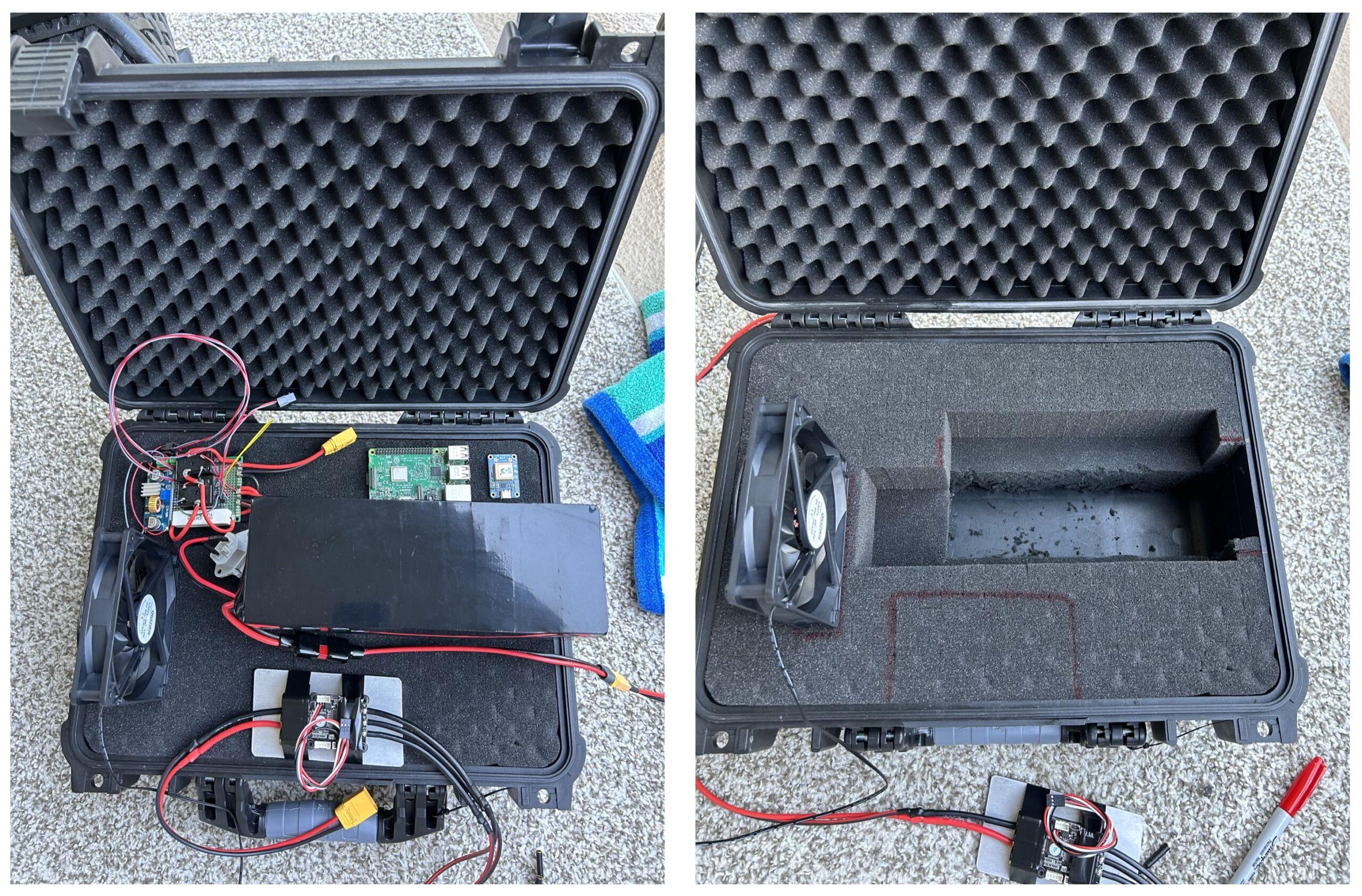
For this first phase of testing, I threw the VESC in the case with the battery out of necessity. As of right now, my only interface to the VESC is the VESC Tool GUI that runs on a computer. I needed to be able to access the USB port to plug the VESC into my laptop. I was hoping the fan would keep the VESC cool but it got a little hotter than I would have liked. In the future, I’m going to move the VESC down onto the fin in some sort of water proof attachment.
Eventually, the case will also contain a Raspberry Pi and GPS module that will be running the machine learning models.
To the Bathtub!
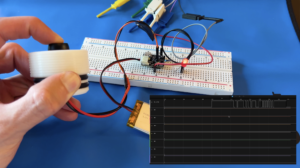
The VESC tool made it super easy to set up the motor controller and I had everything spinning within 15 minutes! There are a ton of great features in the tool like data logging for RPM, current and temperature. The VESC also has a built in Proportional Integral Derivative (PID) controller that can be set in current, RPM or torque mode. I decided to operate in RPM mode. This just means I’m controlling the motor to an RPM setpoint instead of a torque or current setpoint.
PID is a simple but widely used control method. It allows the motor to reach a commanded RPM without overshooting or trying to slam the motors 100% on. This video shows a great visualization how PID controller work. I wanted to tune the PID controller before getting out on the water but didn’t want to wear out the water proofing seals by running the motor in air. It was time to dunk this thing! I took out my rubber ducky and threw it in the bath tub. Unfortunately, the tub was a little shallow and I could only run the motor up to 1,100 RPM before it started sucking in air. I tuned at these speeds the best I could. After a while, I got an RPM response that I was happy with. I optimized for current draw and ensured the motor was reaching my target RPM without any overshoots or oscillations.
After finding a deeper tub, I tried one last high speed test but could still only get up to 1,600 RPM. I would have to tune this thing on the water and hope my bath tub tuning was close enough.
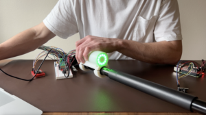
Range Testing / PID Tuning
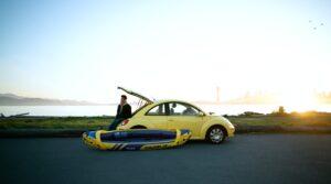
After my bathtub test I was ready to hit the lake! I packed everything up and set out for my maiden voyage. I nearly got stranded and left to paddle two miles home… but more on that later! There were a few objectives to accomplish on this first field test.
- Tune the PID controller at higher speeds
- Characterize my max speed
- Gather current draw / duty cycle data
- Determine range
PID Tuning
I really expected this PID tuning to take up most of my test day. PID controllers are notoriously touchy and you can end up spending a ton of time trying to get things perfect. I am an engineer and we love optimizations after all. But I was pleasantly surprised.
The VESC tool has an awesome “experiment” feature that lets you command different speeds at given intervals. The finished e-kayak will have three modes for speed, low, medium and high. I tuned my PID controller assuming the motor would be ramping from 0 – max RPM (high speed) in four seconds. After some experimentation, I found that my max RPM in water was 2,000 RPM. I’m planning on running all my controls at 20Hz. This means commands to the motor will be sent at 20Hz or 50 ms periods. So to tune my PID controller I assumed a 50 ms command period, ramping from 0 – 2,000 RPM in four seconds. This means we will send 80 commands within the 4 second window (4 / .05 = 80). Which corresponds to a ramp of 25 RPM steps (2,000 / 80).
I set up the experiment to ramp the motors at 25 RPM every 50ms for 4 seconds. Running this, 4 seconds felt like a reasonable ramp rate so I started analyzing the current / RPM data. I didn’t see any major surges in current and the RPM reached its set point with no overshoot or oscillations. Running this a few more times, I decided it looked good enough for what I needed!
I also wanted to make sure the deceleration case looked tuned. I ramped the motor close to my 2,000 RPM max and ran an experiment to decelerate down to 0 RPM in steps of 25 RPM. Again, everything looked surprisingly great! No overshoots, no current surges and no instabilities.
At this point I was ready to gather some current draw data!
Current Draw vs. Duty Cycle
Theory:
Brushless DC motors (BLDC) are current controlled devices. Current has to be driven into each phase coil at a specific time in order for it to magnetize and pull the rotor through the next cycle. Three phase H bridge circuits like the one below accomplish this. M1 – M6 are mosfets which act as voltage controlled switches. The three outputs connect to phases A – C of the motor. Only one high side and one low side fet are on at a time and never the same phase leg. For example, A-Hi and B-Low might be on together which would allow current to flow through M1 and M4. This would cause a current flow into phase A of the motor and out of phase B.
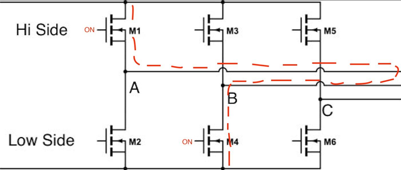
The M1 – M6 fets are controlled with a PWM voltage signal. The higher duty cycle, the longer they are on and the more current can get through. This results in a stronger magnetic field in the motor phase windings. When talking about duty cycle with a BLDC motor, we are referring to this PWM duty cycle to the bridge mosfets.
Testing:
I wanted to collect motor current vs duty cycle data so I could figure out my max RPM and get range estimations.
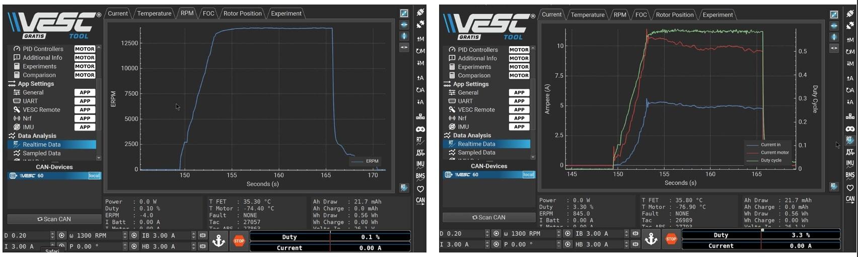
The VESC speed controller can log various parameters like RPM, motor current and duty cycle. The motor rating is 12A and I needed to figure out the max duty cycle I could run the motor at before reaching this 12A limit.
Results:
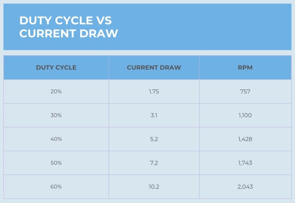
As you can see, I could only get up to about 60% duty cycle / 2,000 RPM before hitting my 12A limit. Looking through the data and based on the speed of the kayak, I’ll have my “low speed” set to 35% duty cycle, “medium speed” to 45% and “high speed” to 60%.
I also gathered some data at various duty cycles with me paddling to see how much the current would drop.
The current only dropped ~.25A in most cases. At the higher speeds it was hard to even paddle. I could barley keeping up with the speed of the kayak. This .25A saving might give another 15 min of runtime depending on the motor RPM.
In the final form, I’ll use some sort of current feedback to ensure the commanded motor speed never causes an over current.
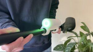
Max Speed
To test my max speed, I used a GPS speedometer app. While this isn’t the most accurate, it was good enough for this project. With one person in the kayak, I maxed out at about 4.2 mph (6.75 kph). And with two people I maxed out my motors at about 3.5 mph (5.6 kph). I was super happy with these results! My goal was to be able to move at a walking pace (3 – 5 mph) and my speed measurements came in right in that range. Even with two people in the kayak, although a little crammed, the pace felt pretty reasonable.
Range
I drastically mis-calculated my range at the start of this project. As I said in the Battery section, I had calculated a range of 1.66 hours based on the motor needing 24V at a 12A max current. Traveling at my max 4.2 mph pace, that would give me a range of about 7 miles. What I forgot about was that the motor is not going to receive the full 24V unless the duty cycle is set to 100%. I could only reach up to 60% duty cycle before the motor started drawing the max 12A. So I was effectively only driving my motor at 60% of the total pack voltage or around ~14V.
Actual Range
During my range test, I only let the motor get up to 10.5A or 50% duty cycle because I was scared of overheating. Running at this pace, the motor power was only 12V 10.5 = 126Wh. My battery is 480Wh. That means My actual range is somewhere around 480Wh / 126 Wh = 3.8 hours! That would equate to a 15 mile range! So I ended up with double the range that I expected! Whoops!
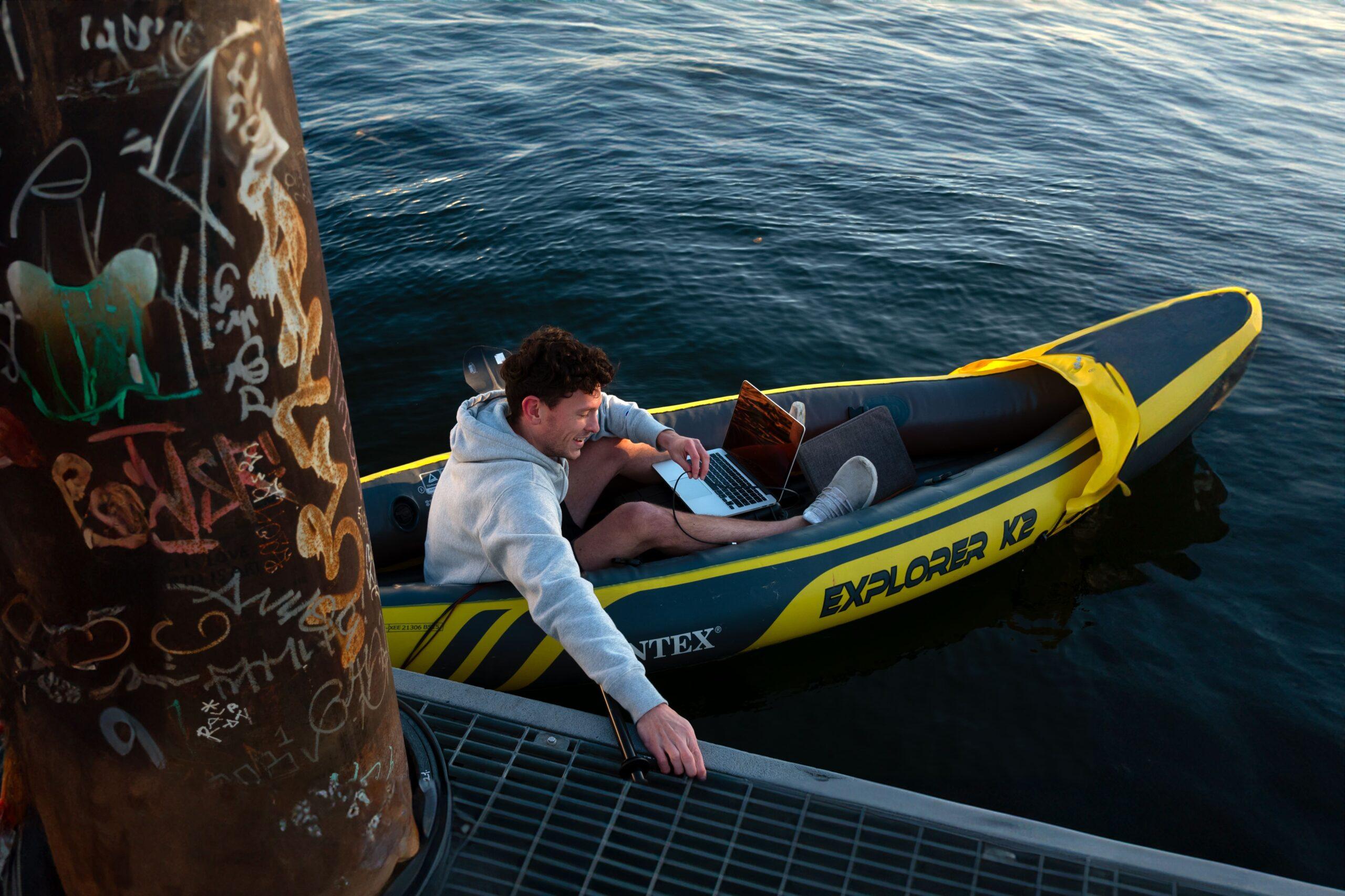
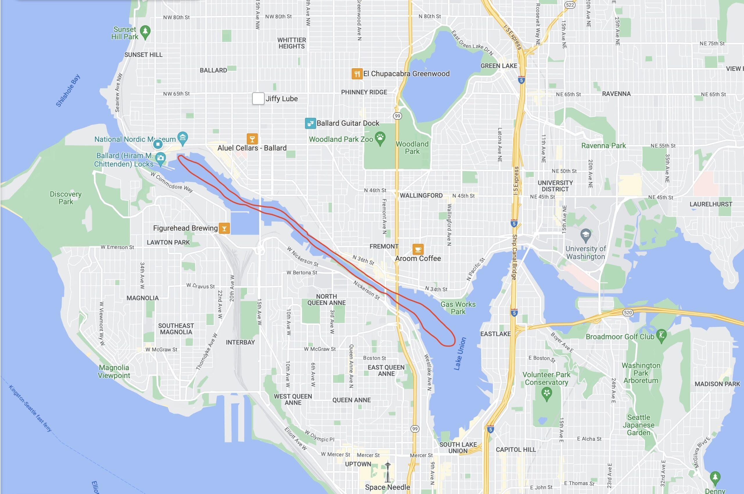
Originally, I had planned on a 4 mile test but after I figured out my range mis-calculation, I decided to see how far I could push it. I started out by the Ballard Locks in Seattle Washington. The Locks are like the Gateway between Lake Union and the Sound. They sit at the end of a man made channel that leads from the Lake to the Ocean. For this test, I traveled the full channel all the way into Lake Union and back again! The full channel is about 8 miles long. All in all, I probably traveled about 14 miles in 3.5 hours and still had plenty of battery left! I did turn the motor speed down to prevent any overheating on the VESC controller.
Motor Scare
On the way back, my motor cut out and stopped spinning. I tried restarting it but no luck… I was stuck paddling 3 miles home. It cut out at the very same time that a big boat wake splashed up over my bow. I couldn’t see any wet electronics but was still worried that something fried. After paddling myself about a mile (gross), I found a public boat launch. I inspected the motor and found a bunch of seaweed in the props.
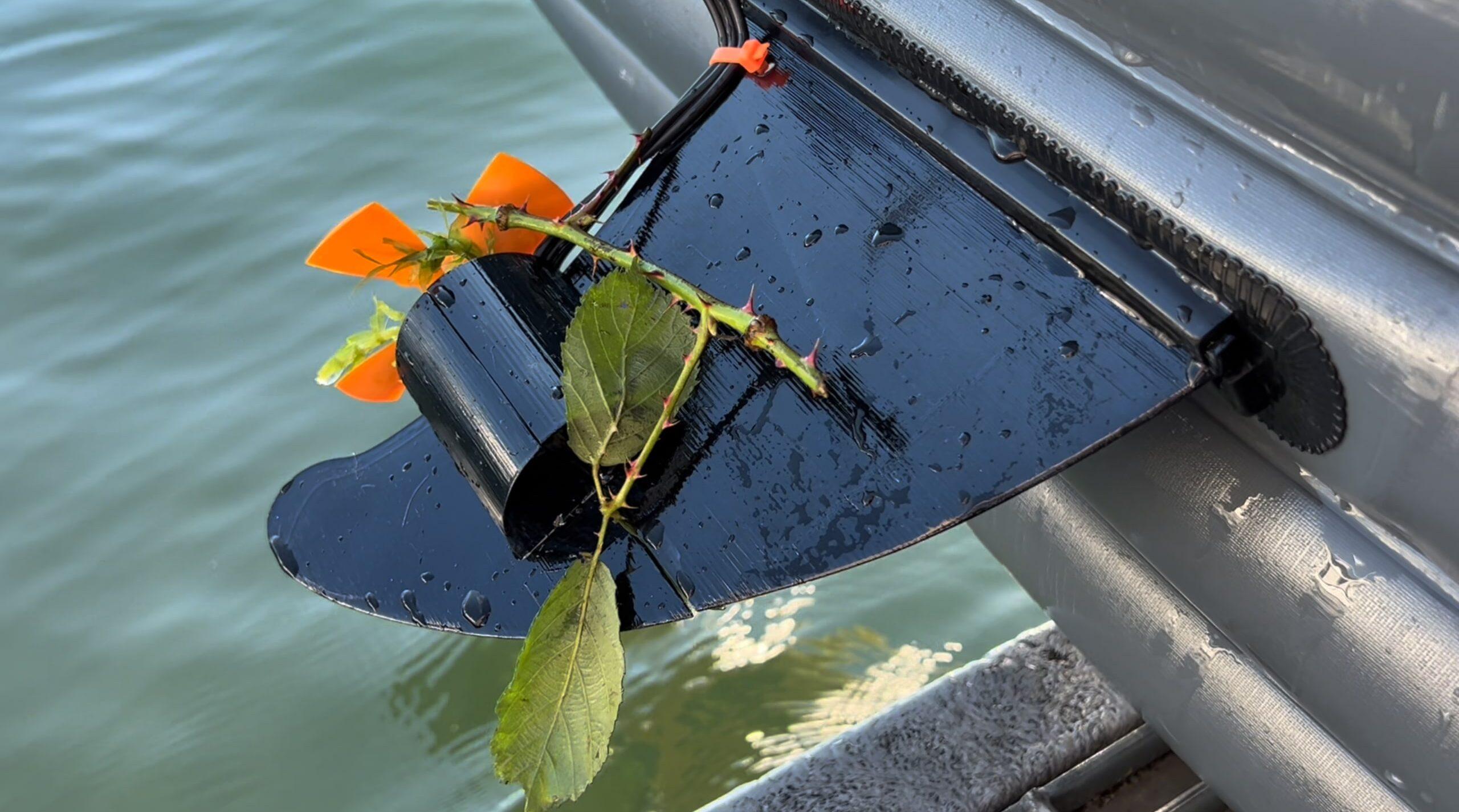
Cleaning them out, everything stated working again. I was relieved. Nothing had broke and I could stop paddling. My e-kayak was fine but I was not prepared for a 4 hour day… I should have put on sunscreen…
Lessons Learned
I learned a lot from my testing. The PID controls tuning should be good enough for my needs, I have a huge range and I don’t plan ahead very well. I was pleasantly surprised by how well everything worked but there are still a few kinks I’ll need to work out.
- The main take away from testing is that with the motor running, the kayak does not sail straight. At all. If left to it’s own devices, it would go in circles.
- Placing the VESC controller in the case with the battery is not the best idea. The VESC mosfets got above 50C (122F). I don’t want any additional heat near the battery as this will degrade it’s lifecycle and performance.
- Seaweed is going to be a big issue. I’ll need to design a prop duct or some other solution to help prevent seaweed from getting caught up in the props.
- With a 24V battery, the motor can only get up to 60% duty cycle before peaking out the input current.
Going Forward
I envision this project in four phases. Phase one was proof of concept / mobility which is now completed. It’s now time to move on to phase two of this project!
Phase 2:
Phase two will focus on final form factor hardware integration. During phase two, I will get my laptop out of the loop and replace it with a Raspberry Pi. The Raspberry Pi will control the VESC based on simple input commands from the oar sensors. The oar hardware cluster will have an IMU (Inertial Measurement Unit), a microcontroller and a battery. For phase two, I plan to use the IMU to detect tap inputs which will control three different speed settings. During phase three, I’ll start to implement some navigation controls.
Phase 3:
During phase three of the project, the kayak will start to get some brains! At this point, the only hardware integration left will be updating the fin to enable servo control. I’ll re-design the fin to integrate a waterproof hobby servo. This will enable me to update the fin angle and control heading. From there, I plan on implementing heading control to keep the kayak steering straight. For this, I’ll use a GPS module connected to the Raspberry Pi for feedback. Once I can show proper GPS control it’s finally time for what we’ve all been waiting for, AI!
Phase 4:
In the final phase of this project, I’ll finally start to implement some AI control. To do this, I will need to use the IMU to gather position / movement data of the oar. The IMU is 9 axis which means it can measure acceleration, rotation and magnetic changes in X, Y and Z axis. I’ll gather IMU data vs kayak GPS data with no motor asset running. This will allow me (or AI rather) to correlate kayak heading vs oar movement. Basically I’ll be able to use the oar IMU data to detect when a user is trying to turn left or right. I’ll feed this data to the fin servo and boom, AI kayak done.
After phase 4, I’ll sail into the sunset and my AI will take over the world.
If you found this content interesting or useful, buy me a coffee!
Donations:
Bitcoin Wallet:
bc1q0vkx34w5y4yt5nq38a4rvk7gvgnxm2xv5lvyft


4 thoughts on “DIY Electric Kayak (16 Mile Range!!)”
Awesome post! Thanks for sharing. A materials list would be a helpful addition, the motor and vesc specifically. Cool project!
Thanks! The motor and VESC I am using are from Flipsky. I think I have an older version of the 5062, waterproof motor. I think it’s an older version because mine is the exact same package, price and prop but had a lower rated power and current. I think the rated current on mine was 12A. The VESC I am using is the FSESC6.7 PRO 70A.
How does the performance and cost of your DIY electric kayak compare to commercially available electric kayaks on the market? Have you considered selling your design to others looking for a budget-friendly electric kayak option?”,
“refusal
Haven’t really considered it yet. Once I get the paddle assist and steering detection working well, I might take it to some local kayak rental shops and see if there is any interest! I think a lot of the electric kayaks on the market right now are either above $2,000 and geared toward fishing, or are super cheap / low quality from China.