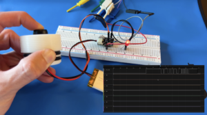
In Part Two of my e-kayk series, I started on the kayak remote control that mounts to the paddle. I showed the bread boarded electronics, firmware and teased the 3D printed housing. Now I’ve got it ready for prime time. In this part three, we shrunk down some of the electronics with a few custom PCBs, finished testing the 3D printed housing and packaged everything together!
Summer is quickly approaching here in Seattle and I’m one step closer to setting sail! Be sure to sign up for my newsletter! I share project updates, spotlight other makers and anything else I find interesting! If you’re a maker at heart, I promise this is for you.
If you haven’t seen Part One or Part Two, check them out!
Shout out to PCBWay for sponsoring my PCBs and 3D prints for this project!!
Phase Three
Phase three is all about finalizing the paddle controller hardware. In this post, I’ll show you how I went from a messy breadboard to a full blown, professional prototype.
Check out the full video on my YouTube channel!
If you want to see more, consider buying me a coffee! Every small donation is like a little boost of motivation and helps keep the project afloat!
3D Prints
In part two, I showed a bit of the 3D printed housing but there was a lot more work that went into this thing behind the scenes. My engineer / designer friend Jordan Godoy worked his magic and created a whole custom latching mechanism. I’ve never been one to enjoy the intricate, puzzle like, mechanical designs but he is perfect for it!
Initial Designs
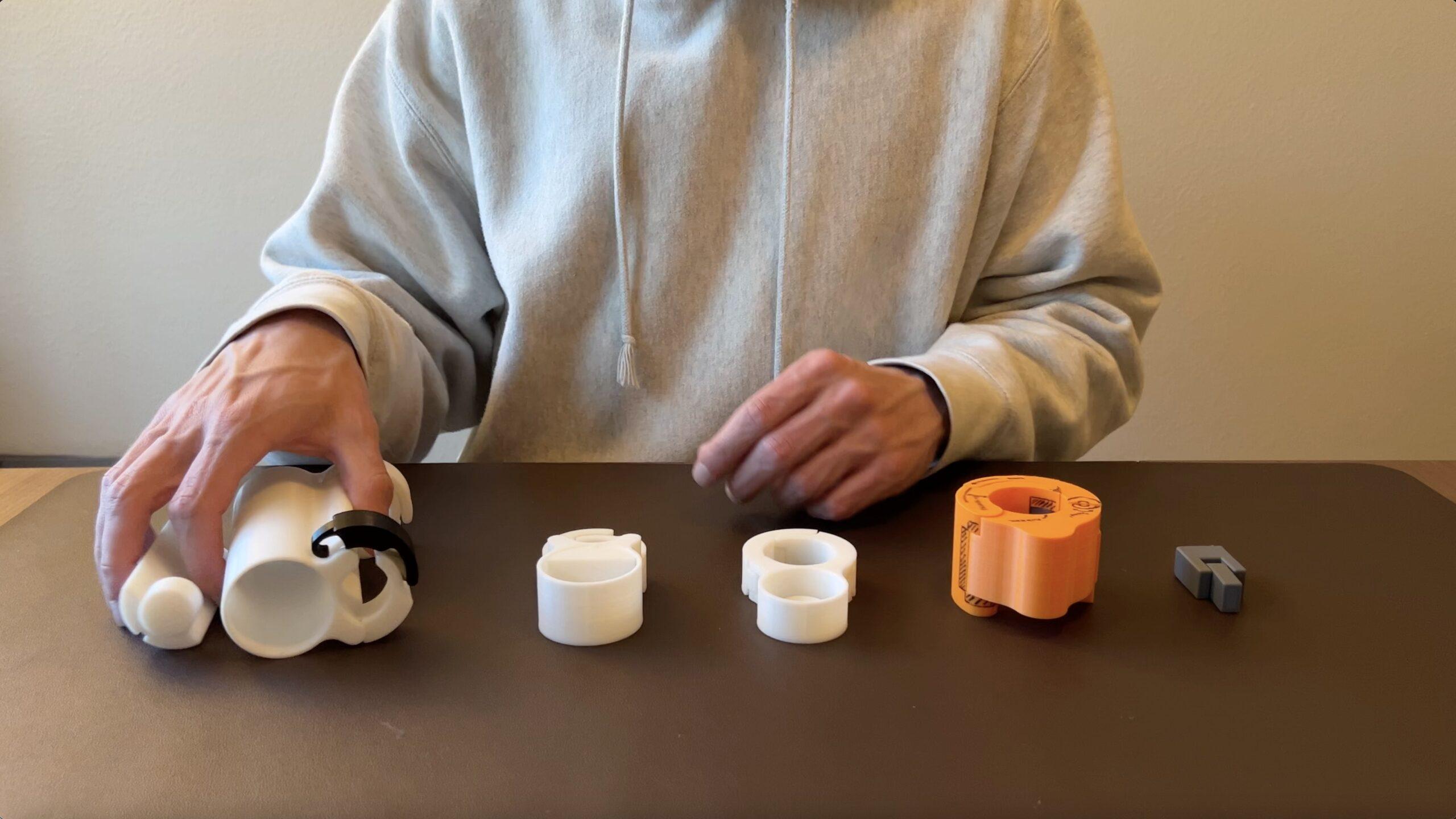
We started out brainstorming the best ways to attach a housing to the paddle and what the housing should look like. To start with, we drew our inspiration from the bar bell clamps that you use when squatting. The first design seamlessly integrated all the electronics into the actual clamping structure.
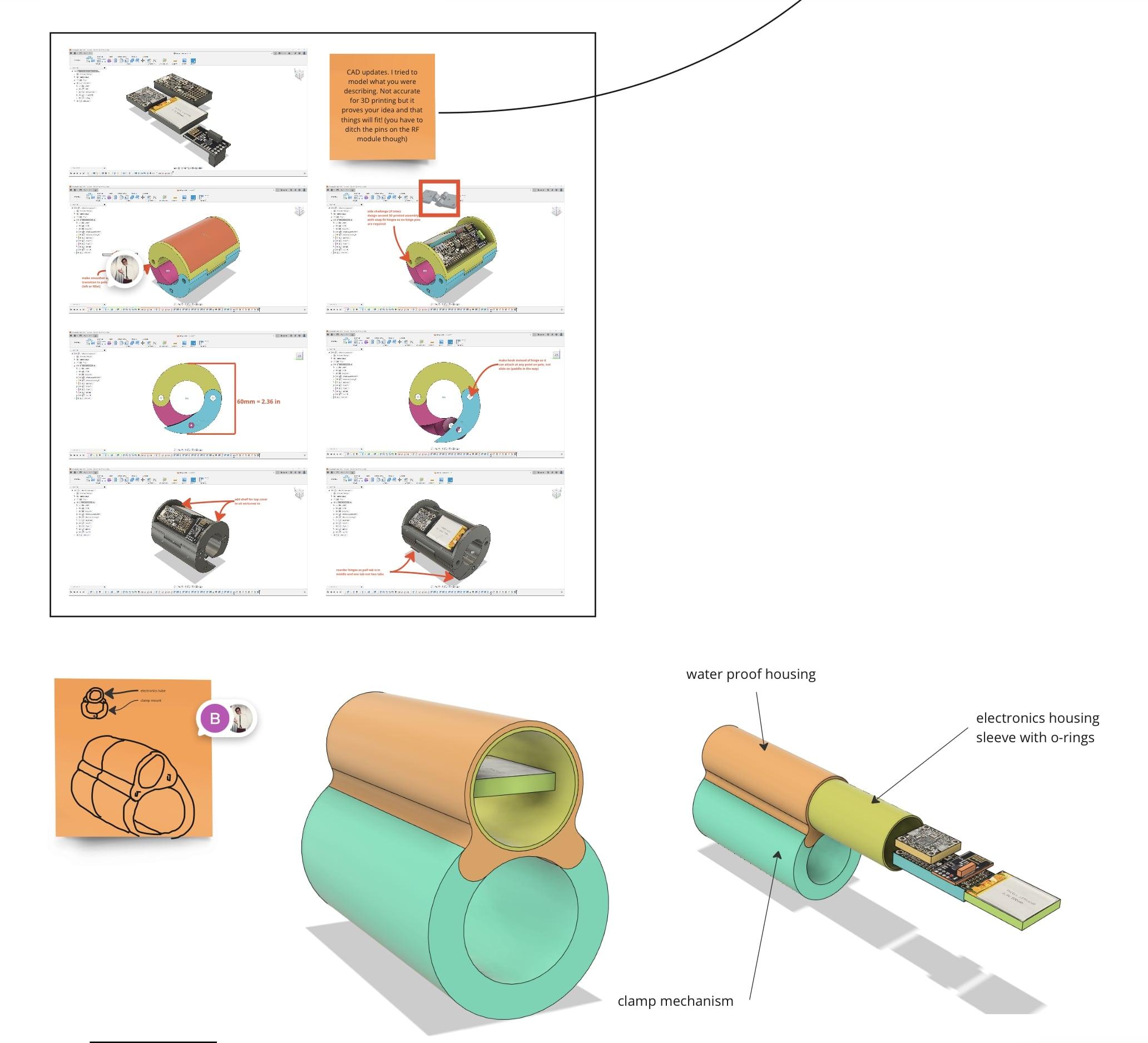
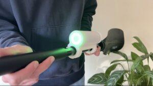
Although this design looked super clean, we realized that we have to water proof this thing somehow. And decided it would be way easier to waterproof a tubular design with O-rings rather than custom shaped gasket. At that point, we transitioned to our second design iteration. A cylindrical tube sitting on top of the clamping structure where all the electronics could slide inside. It was also at this point where I realized I needed some sort of display for the user and the new cylindrical shape was perfect for an LED ring.
After these design choices were finalized, Jordan got to work printing, testing and iterating.
Iterate, Iterate, Iterate
To start with, he experimented with snap fit prints and got the tolerances dialed in for strong joints. From there, he tested the first design but it didn’t have enough clamping force. After studying every clamp he could find in his house, he came up with a working hook clamp design. Once the new clamp proved it could work, he dialed in every variable like hook pitch, spacing to allow ease of unlatch, etc.
Lastly, Jordan thought of a locking shelf that would slide into the housing providing a space for the the electronics and LED ring. This will ensure the IMU is always in the exact same place which will be very important when I go to train the ML models.
3D Print Testing
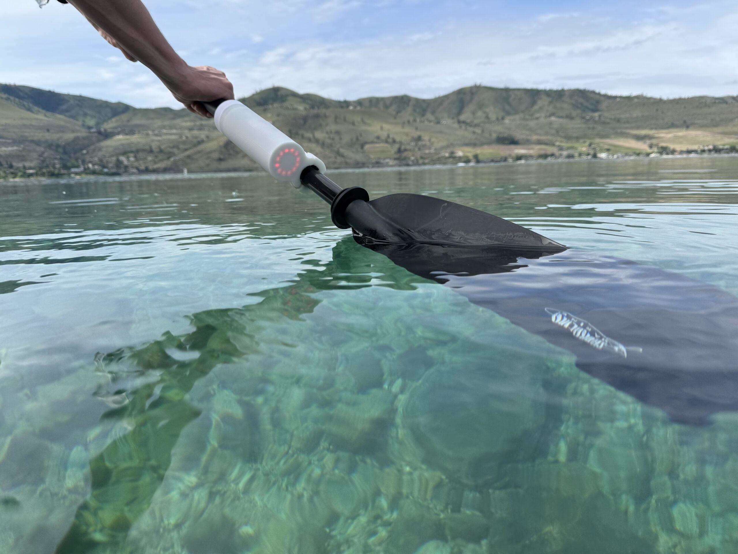
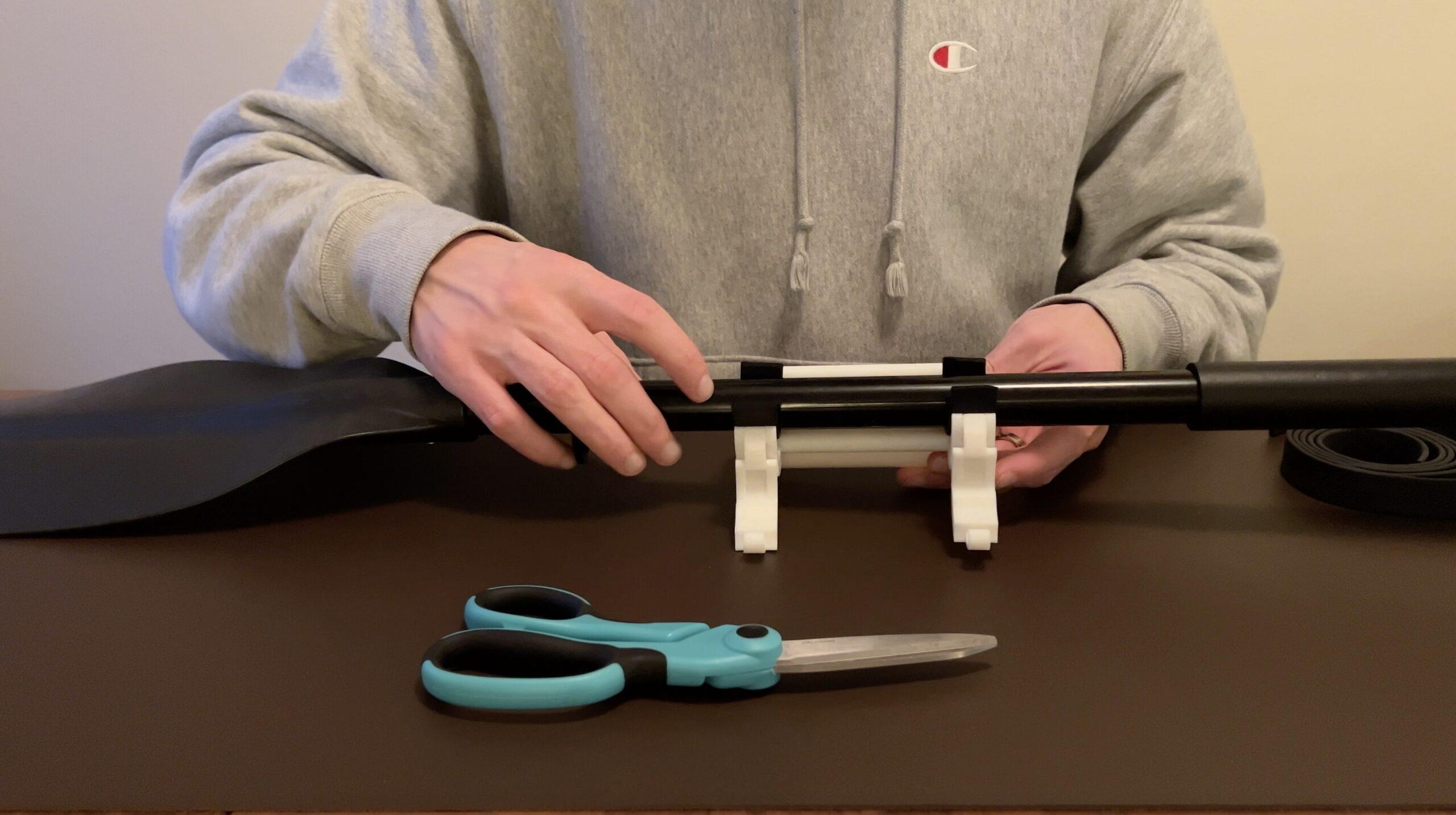
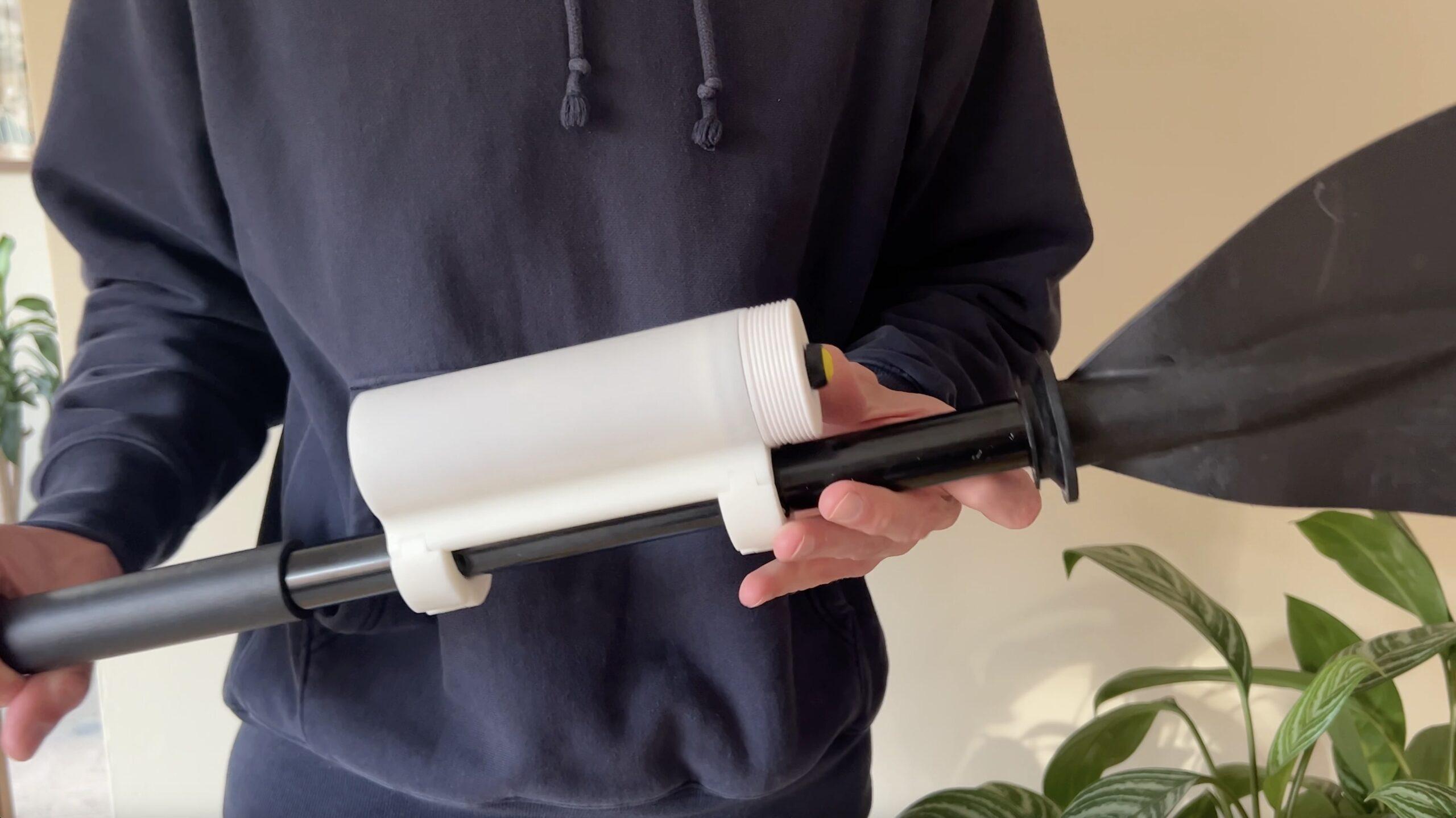
Once the 3D printed housing was finalized, it was time to test on the real paddle.
I bought a couple different rubber / foam weather proofing strips to line the clamps in order to give it more friction and seal. The first neoprene rubber strip was too thin and didn’t provide much squish in order to get a tight grip. The second foam strip worked like a charm!
After the successful integration test, there was one more very important test to do. Water proofing. I put the two O-rings on and to my surprise, the lid seemed to make a tight seal. I installed and sealed the push button with hot glue.
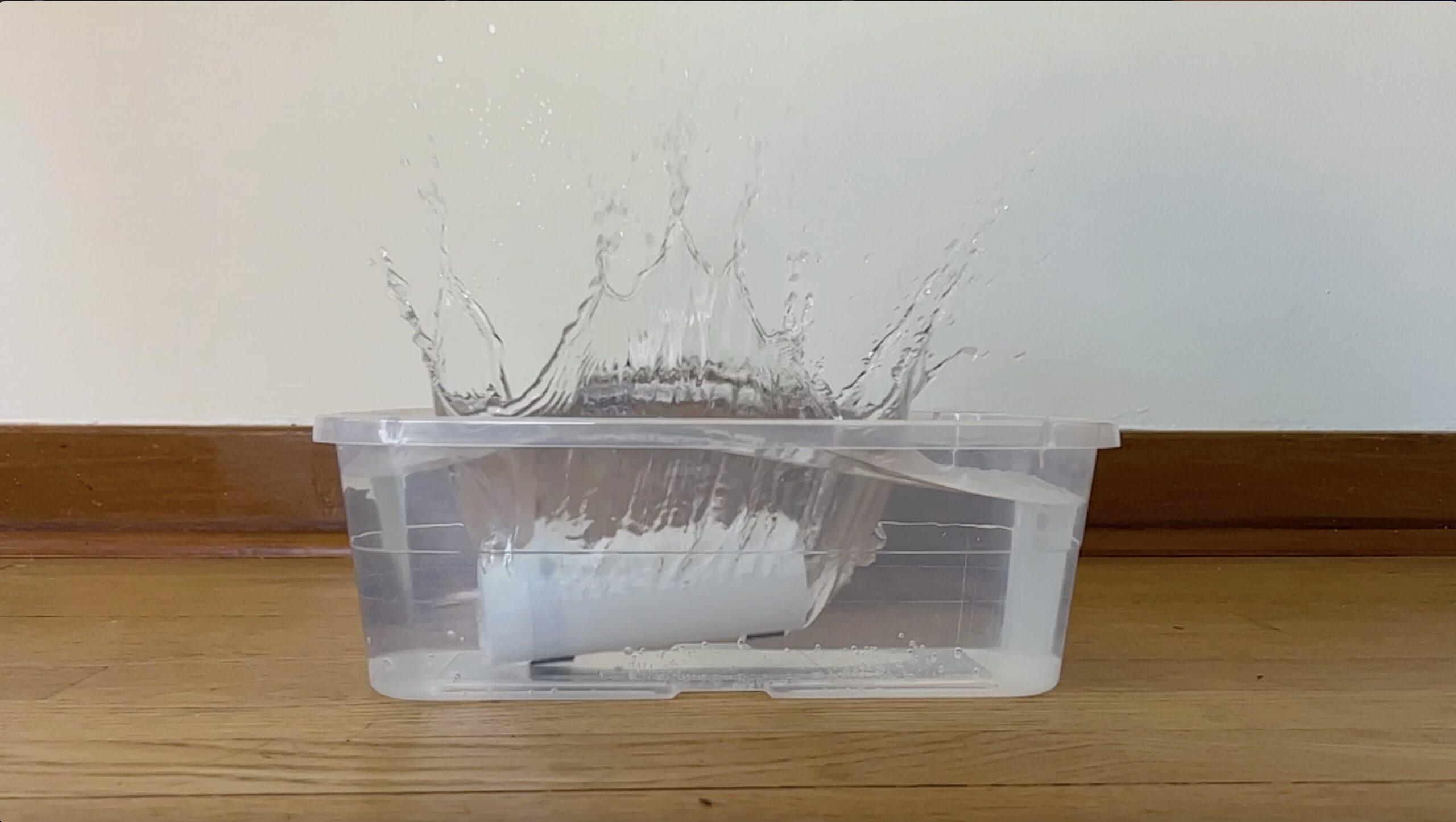
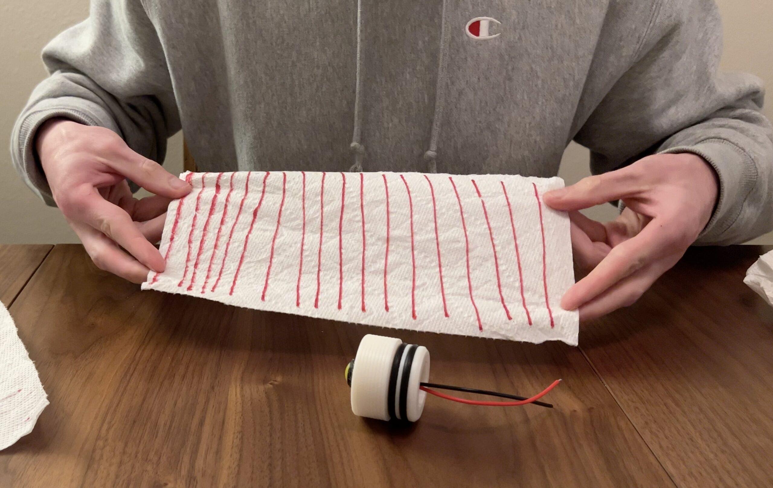
next, I colored a paper towel sheet with sharpie and wadded it into the tube, sealing it with the lid. Submerging the housing into a tub of water, I repeatedly pushed the button and tapped on the housing. I weighed down the housing and let it sit in the water bath for ~20 minutes. Pulling out the paper towel, I saw no smudged sharpie! Everything was dry.
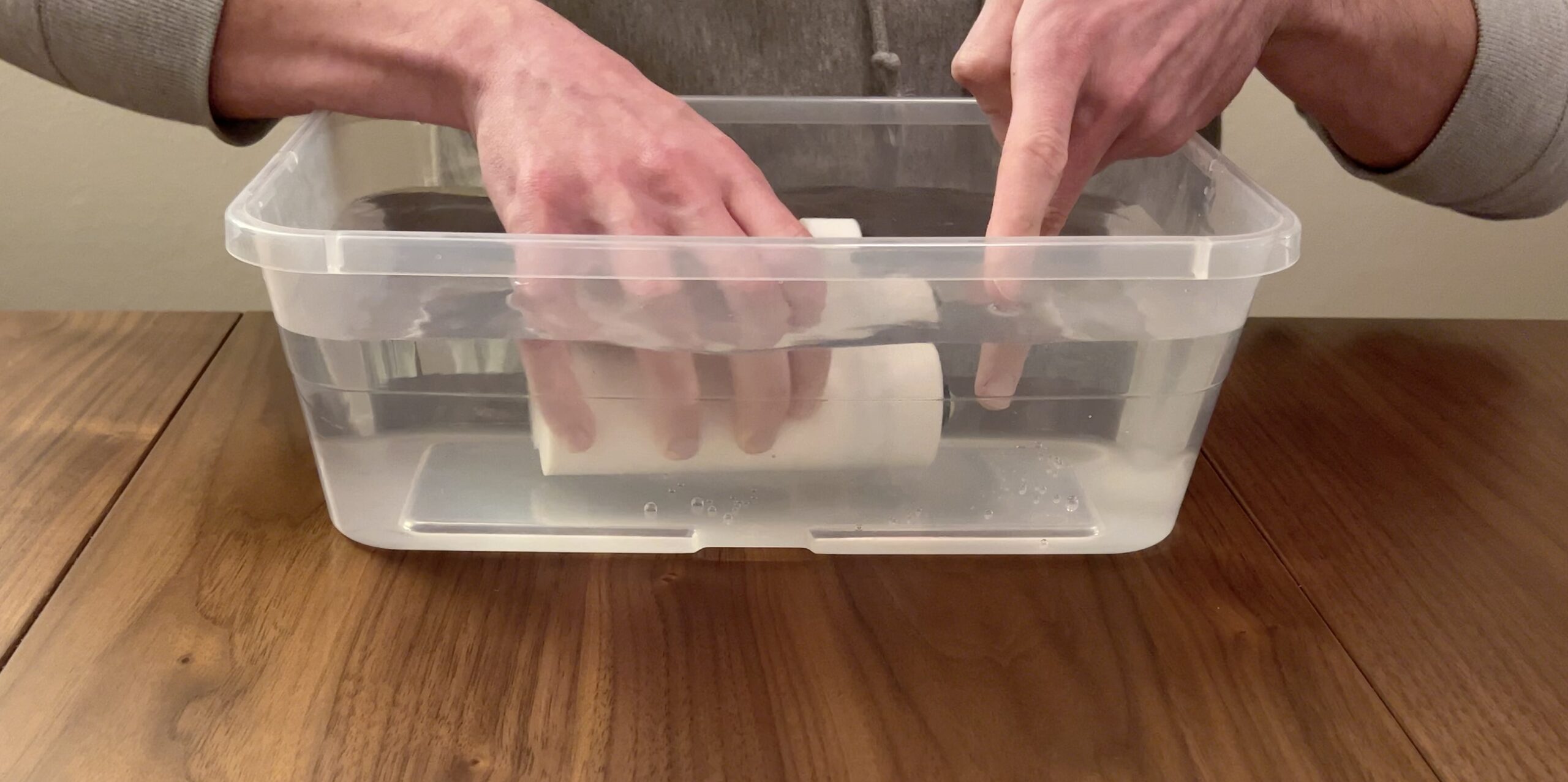
Before taking this thing out on the water, I’ll cover the whole thing in XTC-3D sealant to further water proof it.
PCBs
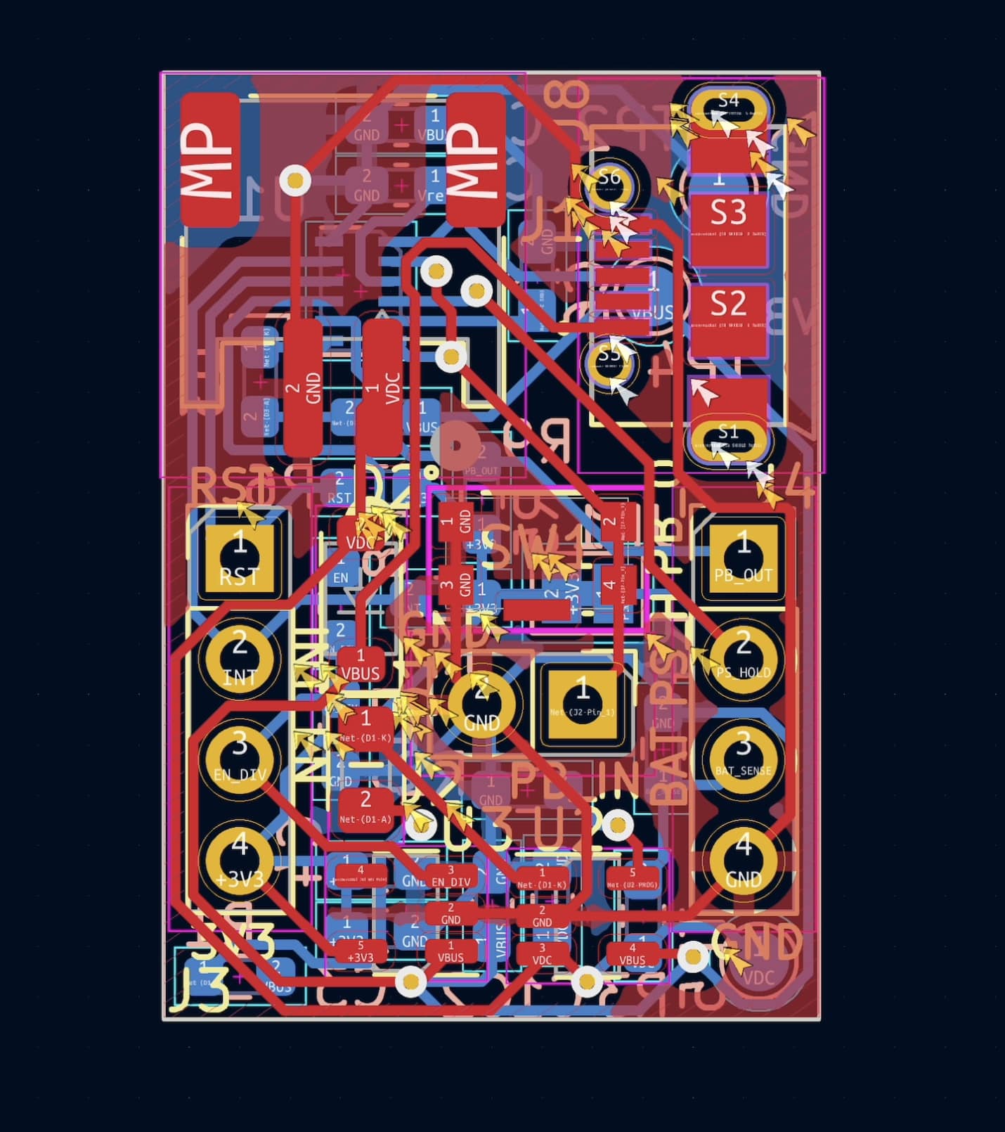
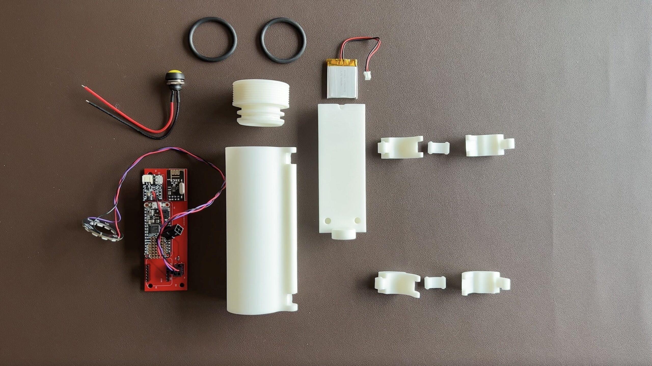
With the 3D prints tested and working, it was time to shrink down the electronics to fit inside. We decided to create two PCBs, one daughter board that all other breakout boards would mate to, and a new breakout board for the on/off controller IC.
Huge thanks to PCBWay for making this project possible! They sponsored the PCBs and new 3D prints for this phase! If you have not heard, they have amazing manufacturing capabilities that are accessible to makers with low costs and fast shipping!
Smart Click On/Off Controller PCB
I am calling the on/off controller breakout the “SmartClick”. It allows me to use a single button as a power switch and a regular input button! It’s got a build in battery charger and allows a super clean, minimal UI for any project! I’ve got a whole other Instructable deep diving the SmartClick and how it works. Let me know if you’re interested in using the SmartClick in your own projects! I will open source the design but might also put them up on my Tindie store if anyone is interested.
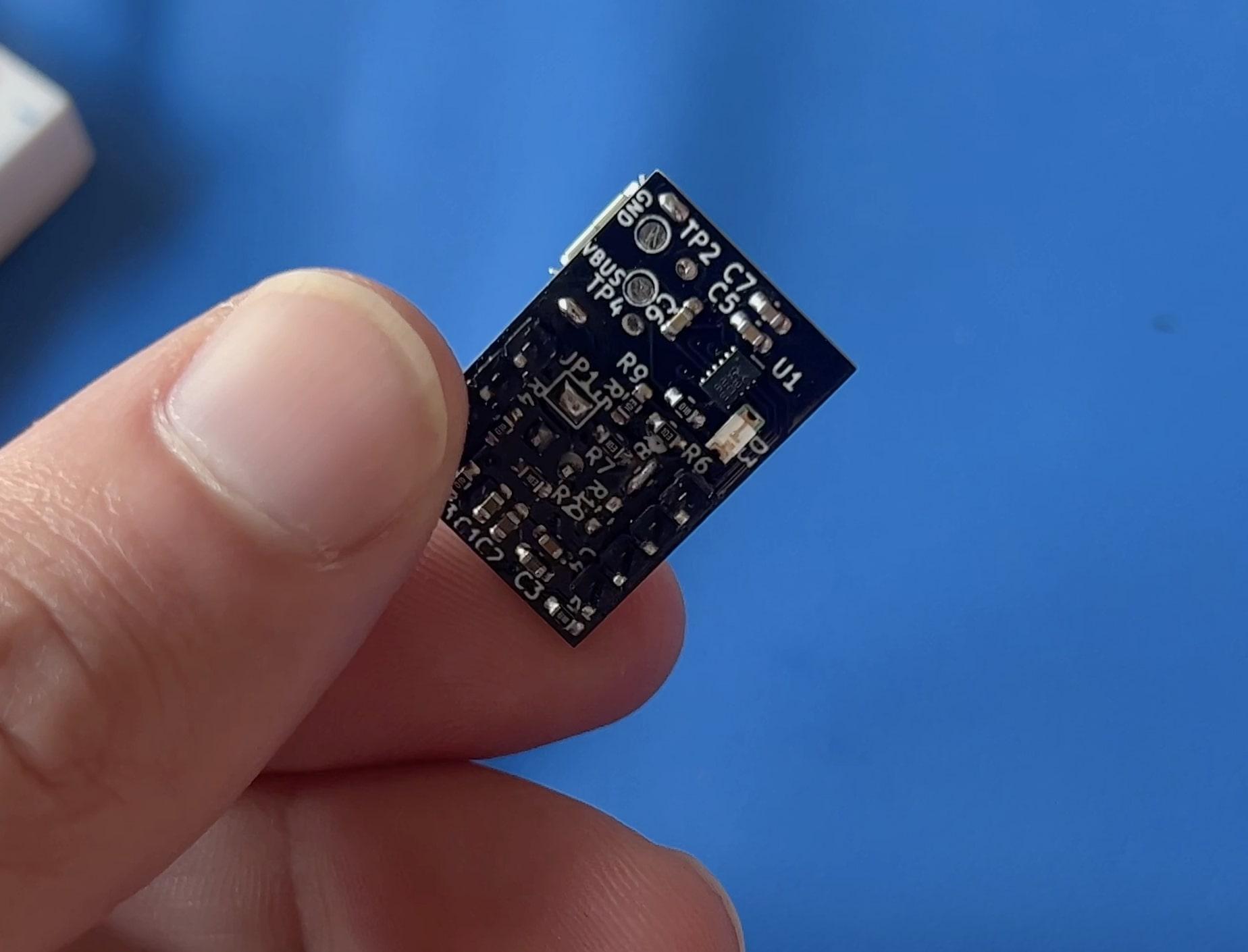
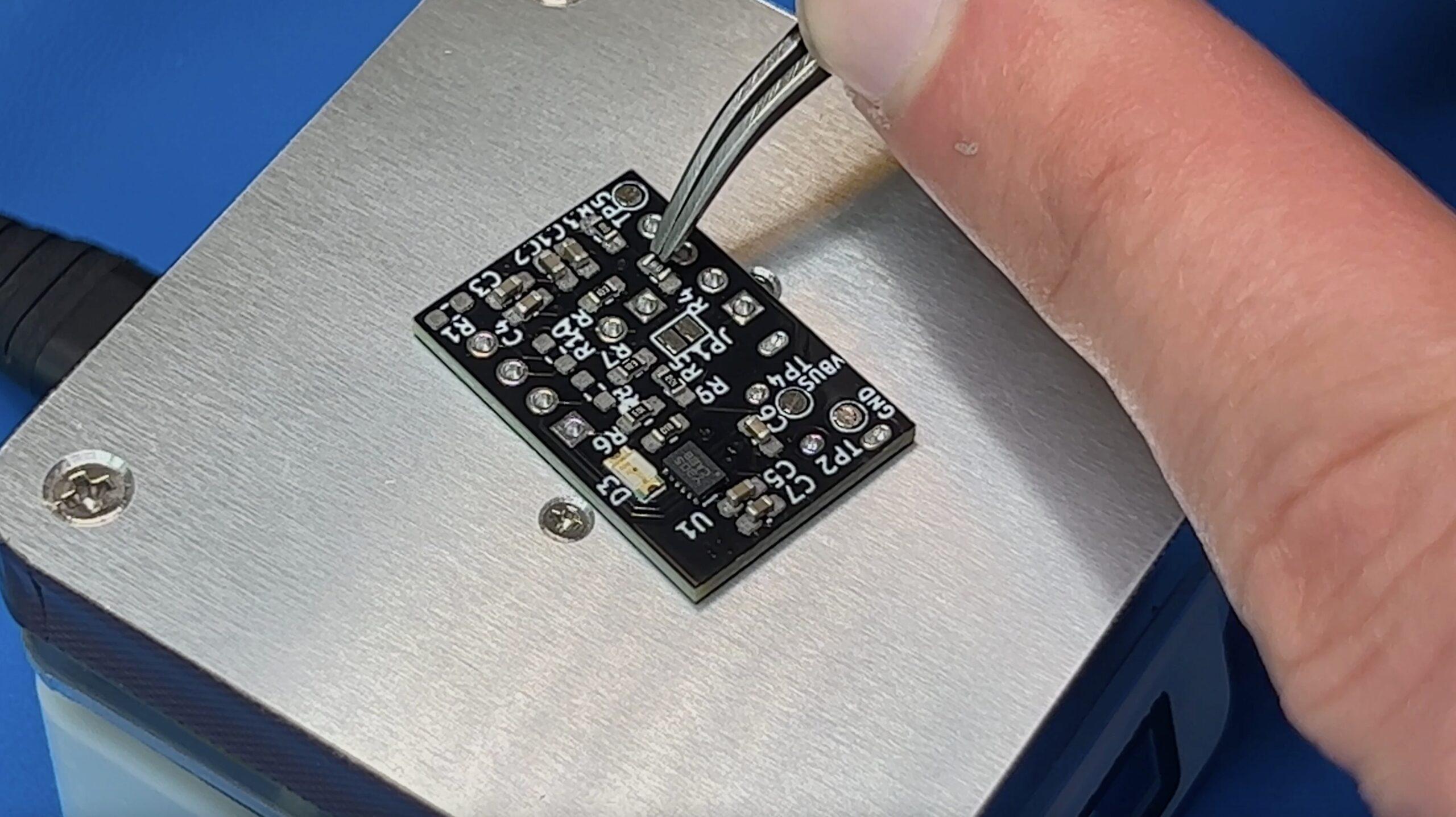
This was the first time I’ve done stenciling and hot plate soldering and it went really well all things considered!
Size Constraints
Combining all the breakout boards onto a single daughter board took up more space than we were expecting and we had to lengthen the 3D printed housing a bit. In a future revision, I may create more custom PCBs and focus on reducing the sizes as much as possible. As a designer, Jordan is always looking to push the limits on size constraints and usability but for now, the chunky electronics will be the bottle neck.
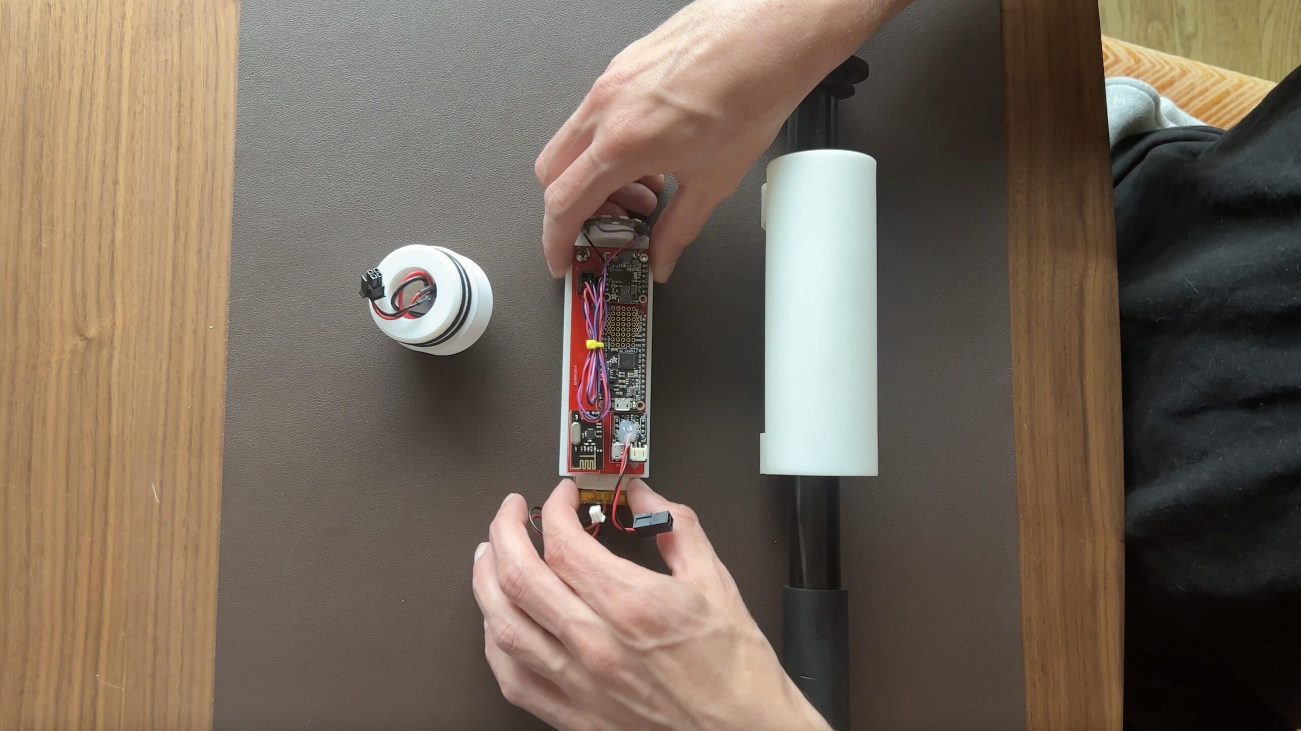
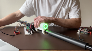
Final Integration
The daughter board worked perfectly but the SmartClick had a few bugs. After finding and fixing (most of) the bugs with the Smart Click PCB, I received my new elongated 3D prints from PCBWay. I melted some M4 threaded inserts into the 3D print and started installing all the final hardware. I could not wait to see this thing secured to a paddle for the first time with real electronics.
The Pi will eventually be commanding motors and running machine learning models. But for now, I got the Pi set up to log IMU data in order to show paddle tracking capabilities.
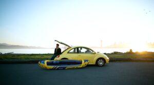
I’m so close to getting this thing back in the water for summer! I’ve just got to get the Pi commanding my motors and I’ll be ready for my first test of the summer!
If you would like to support me and this project, please consider buying me a coffee! Every little donation helps keep this thing afloat! Also subscribe to my newsletter below! It’s for curious minds, makers and anyone who shares a love of electronics.
If you found this content interesting or useful, buy me a coffee!
Bitcoin Wallet:
bc1q0vkx34w5y4yt5nq38a4rvk7gvgnxm2xv5lvyft