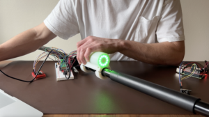
As mentioned in my DIY e-kayak series, I have been working on a breakout board for a cool little button circuit I found! For the kayak controller, I found myself wanting a single button UI that controlled power and provided inputs to the system. I wanted to save space and keep a minimal design so having two buttons was off the table. That lead me to an interesting chip, the PMIC (power management IC) on/off controller.
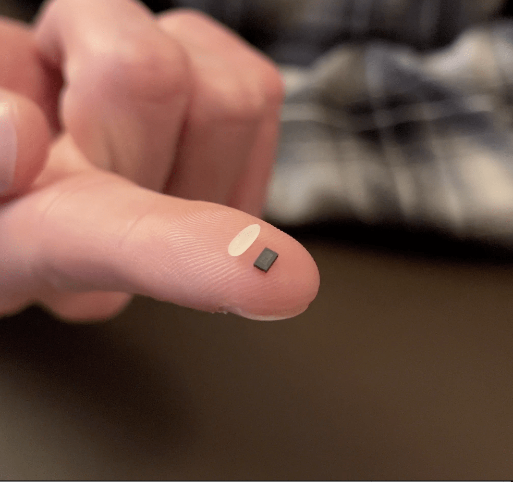
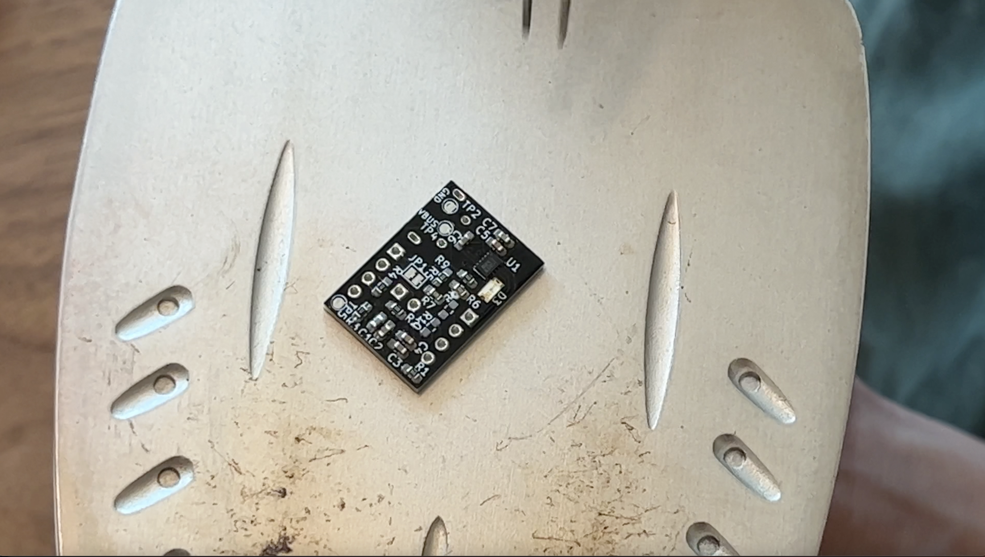
This little chip was exactly what I was looking for. And when I say “little chip”, I’m not exaggerating. This thing is literally smaller than a grain of rice. That made soldering / prototyping very difficult. That’s why I decided to create a PCB breakout board so that I can re-use this circuit in projects moving forward and take advantage of the small form factor.
Here is a breakdown of my prototyping, testing and creation of the “SmartClick” PCB.
Big thanks to PCBWay for sponsoring this project! Check them out if you need anything manufactured. From PCBs to 3D prints to Injection Molding, they’ll have you covered! Get $5 off your first order with my link!
Check out my YouTube video deep diving all the technical details!
Breakdown
This project is completely open source and all designs can be found in the git repository.
With this breakout, the first press of a button will enable a 3.3V regulator. Any button presses after this will act as regular inputs and a long button press will disable the 3.3V regulator.
I wanted this breakout board to handle all my power needs for any new project I create moving forward. That meant it needed to have the on/off controller but also needed a way to re-charge a battery. I designed the breakout so it could charge a single cell LiPo battery and provide battery level indication. I based the charge and voltage regulator designs off the Adafruit feather power scheme.
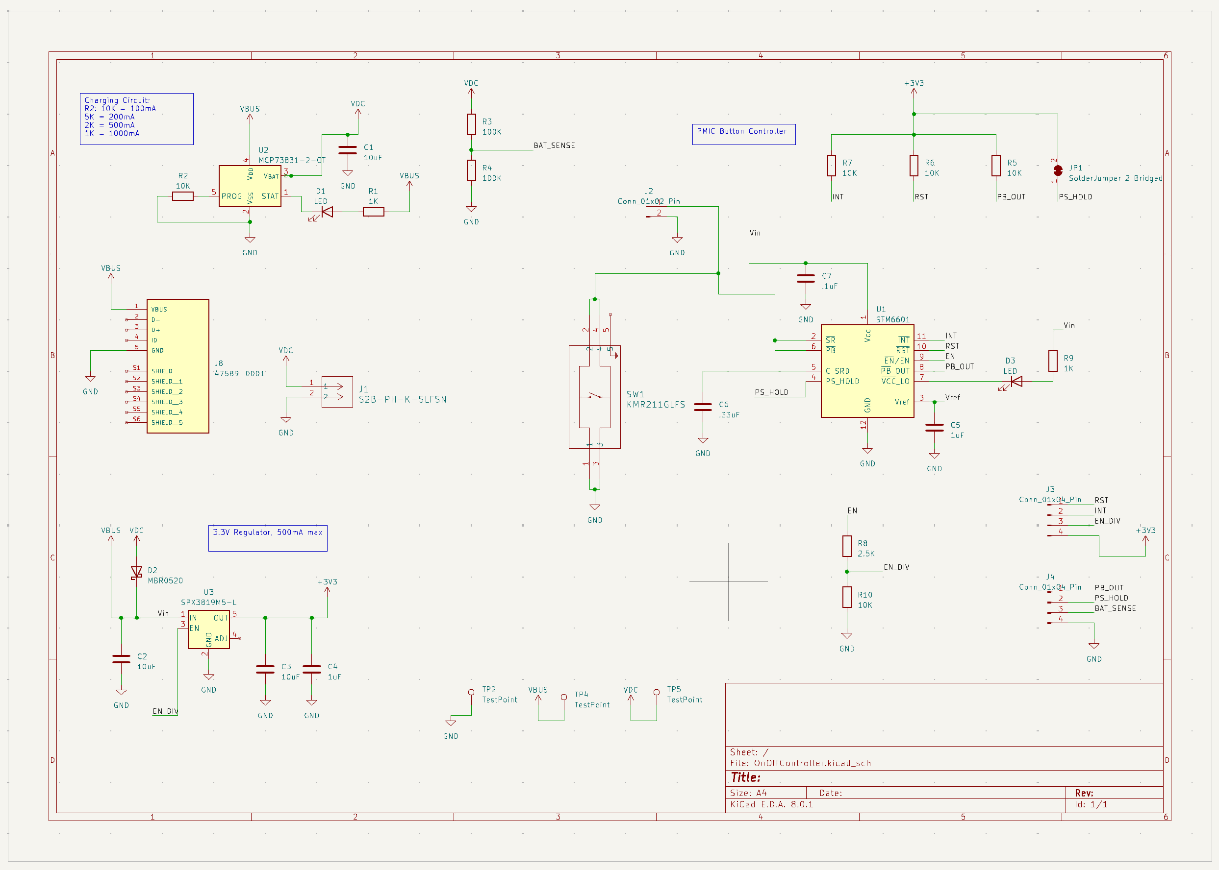
STM6601 On / Off Controller
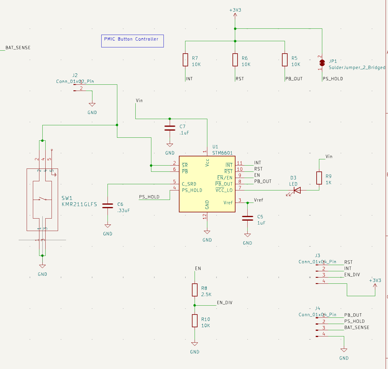
The brain of this board is the STM6601 on/off controller IC. It monitors the push button and enables / disabled power, all while drawing .6 micro amps of current in sleep mode and 6 micro amps during regular operation.
The chip works by idling in a deep sleep state looking for push button activity to wake up. It can run in sleep mode for decades off of a single cell LiPo.
Power Enable
The first push of the button brings the IC out of sleep mode and sets an enable pin high. This enable pin is tied to a 3.3V regulator. When enable goes high, the regulator turns on, providing 3.3V out. A long push of ~3.3 seconds sets the enable pin back low, which turns the 3.3V regulator off, and places the chip back into deep sleep.
Interrupt / Push Button Out
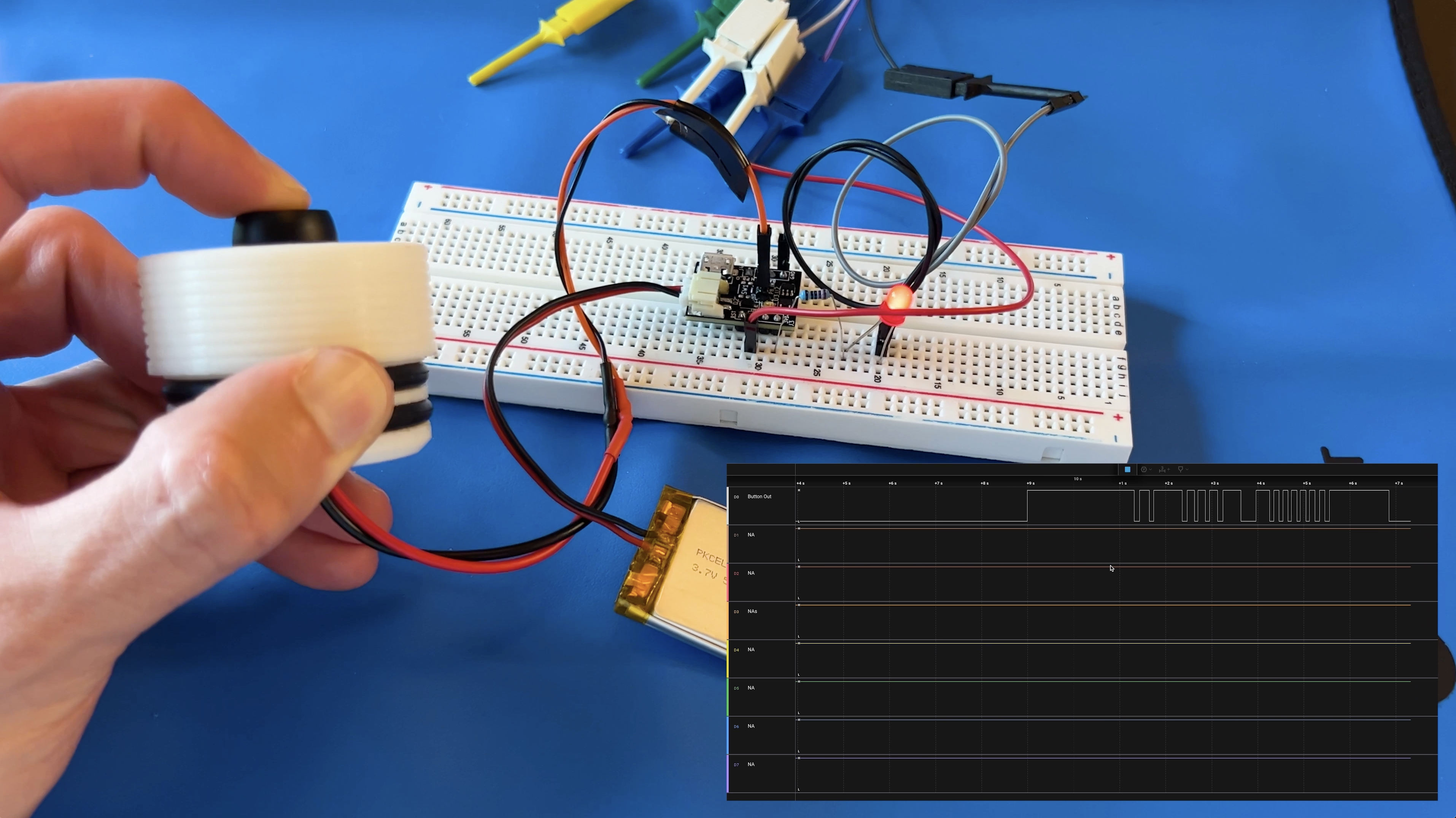
The breakout board has two output signals that are used to detect additional button presses. Once the IC is awake, any button presses result in the INT (interrupt) pin pulsing low. An under voltage condition can also cause the INT pin to pulse low so the PB_OUT (push button out) pin can be used to verify if an interrupt was triggered by a button press or under voltage condition.
The following pins are open drain outputs: PB_OUT, INT and RST. This means they are pulled up to 3.3V by default and are active low.
Push Button Input
The SmartClick breakout board has a small onboard push button. Jumper pins 9 and 10 also provide a place to wire in your own external push button.
Battery Charger Circuit
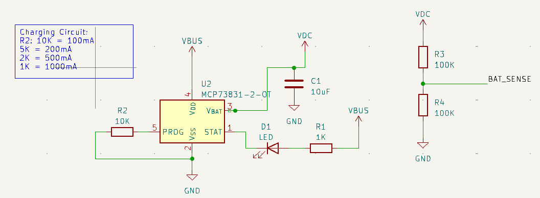
I wanted to drop this breakout board into any project as a complete power system solution. That meant I needed a built in battery charger.
The SmartClick has a MCP73831, single cell LiPo charger IC. It is configured to charge at 100mA and has LED indication during charge. The BAT_SENSE (Battery sense) pin can be read by a microcontroller to measure the battery voltage.
The battery sense pin is connected to a resistive voltage divider which scales the battery voltage in half. This provides a safe voltage level to be read by any microcontroller. The battery input and micro-USB charge port are diode OR’d together so the circuit will still get power during charging. Because of this diode, the battery sense pin sees a .7V drop. So the equation to convert the battery sense pin output to true battery voltage is: (BAT_SENSE_V * 2) + .7
3.3V Regulator
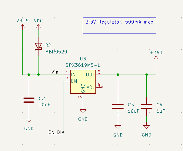
As mentioned, the SmartClick breakout has a built in 3.3V regulator which is enabled / disabled by the STM6601. The regulator is a SPX3819 and provides a max output current of 500mA.
Soldering
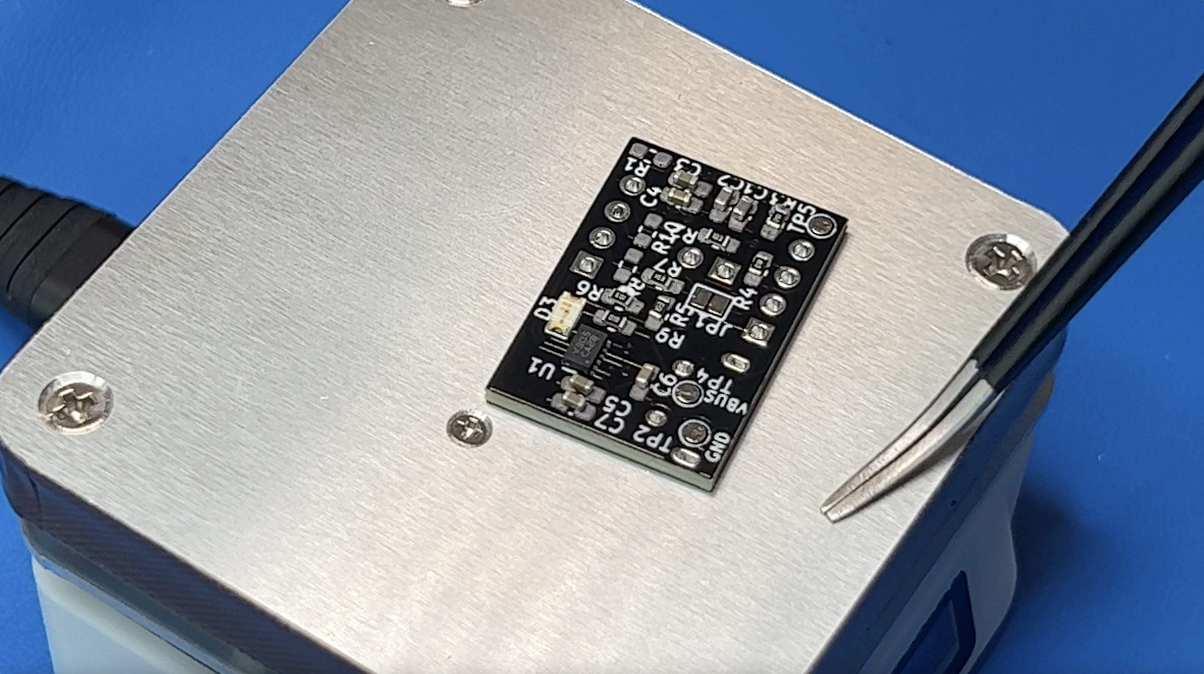
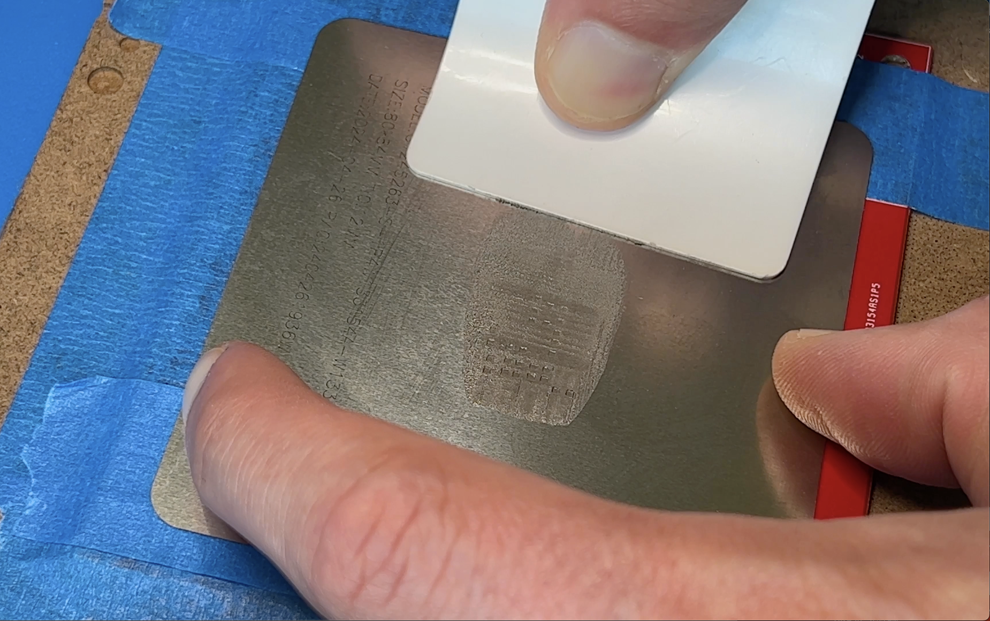
This is the smallest PCB I have ever fully assembled and my first time trying out stencils. So it was the perfect opportunity to buy a new tool, this hot plate. I spent about an hour stenciling and meticulously placing components. I plugged in my new hot plate anddd I smelled the all too familiar smell of burning electronics. The manufacture sent me a replacement but I’m impatient and I had a board covered in wet solder paste. Sooo I grabbed the iron instead. Now the iron worked great but I have one major piece of advice. Think through how you are going to remove the board before you start… My hand slipped and all my tiny 0603 parts went everywhere. (watch my YouTube video to see my sadness).
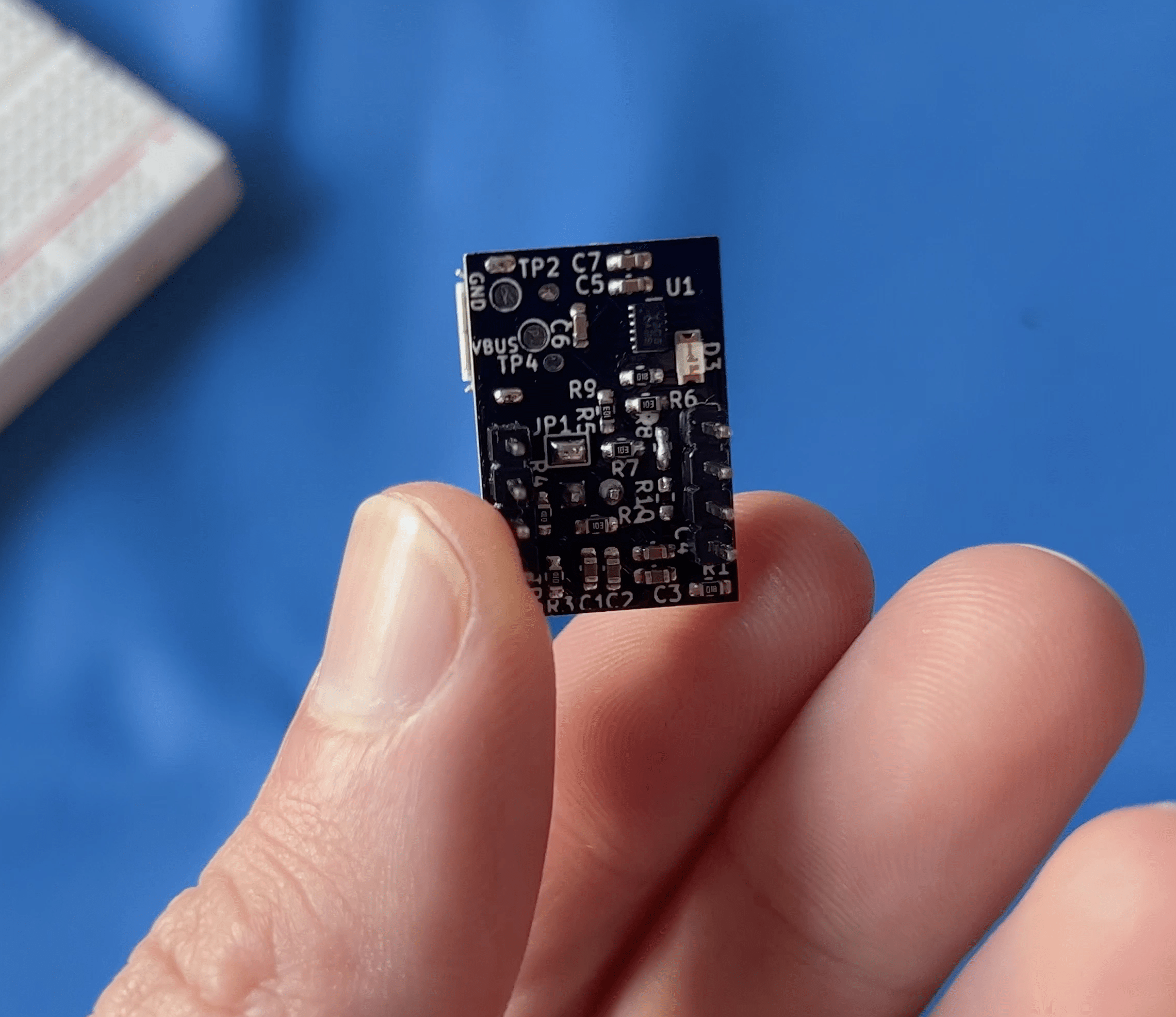
I got the replacement hot plate and it worked great! I re-stenciled my board and this time didn’t do anything stupid. Everything soldered down right in its place. I hand soldered the top components and I was ready to test.
Testing The PCB
Button Issues
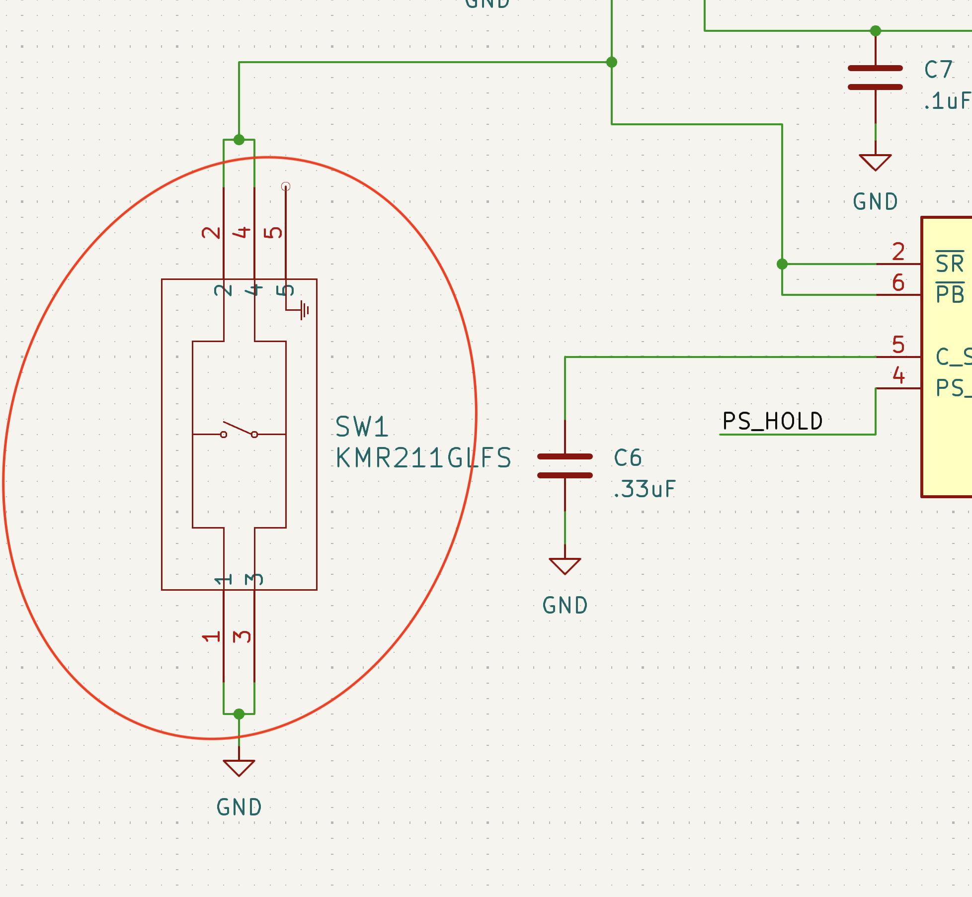
After checking for shorts, I plugged in my battery. As soon as plugging in the battery, I saw the 3.3V output go high. This should have idled off until a push of the button. Turns out, I did do something stupid. Again. Looking closer at my schematic, I routed the on-board push button as a short circuit. So as soon as the battery was plugged in, the on/off controller detected a button push and enabled the 3.3V regulator. I desoldered the on board push button and will have to use the external header pins for now. After doing this, the button circuit worked great. I could turn on and off power and see button press interrupts being fired off.
Charge Circuit
Next was testing the battery charge circuit. I plugged in the micro USB cable to provide 5V and immediately saw the charge LED dimly lit even though no battery was connected. Plugging in the battery, the LED got brighter so I thought the charge IC was stuck in some sort of loop, falsely detecting a battery, then realizing there isn’t one connected and repeating that cycle causing the LED to look dimly lit. I was very confused since I literally copied Adafruits design that is used on thousands of boards.
At first I thought the diode ORing circuit between the battery and USB power was leaking current but I still had the same issues after removing the diode. I tried decreasing the bypass cap on the battery detect input, increasing the bypass cap, removing the bypass cap. Nothing worked. Then I got smart and grabbed a spare Feather board I have lying around. I plugged in the micro-USB and then the battery and wouldn’t you know, I saw a dimly lit, flashing charge LED. Turns out if you plug in the battery FIRST, then the micro-USB cable, everything charges as expected.
Enable Divider
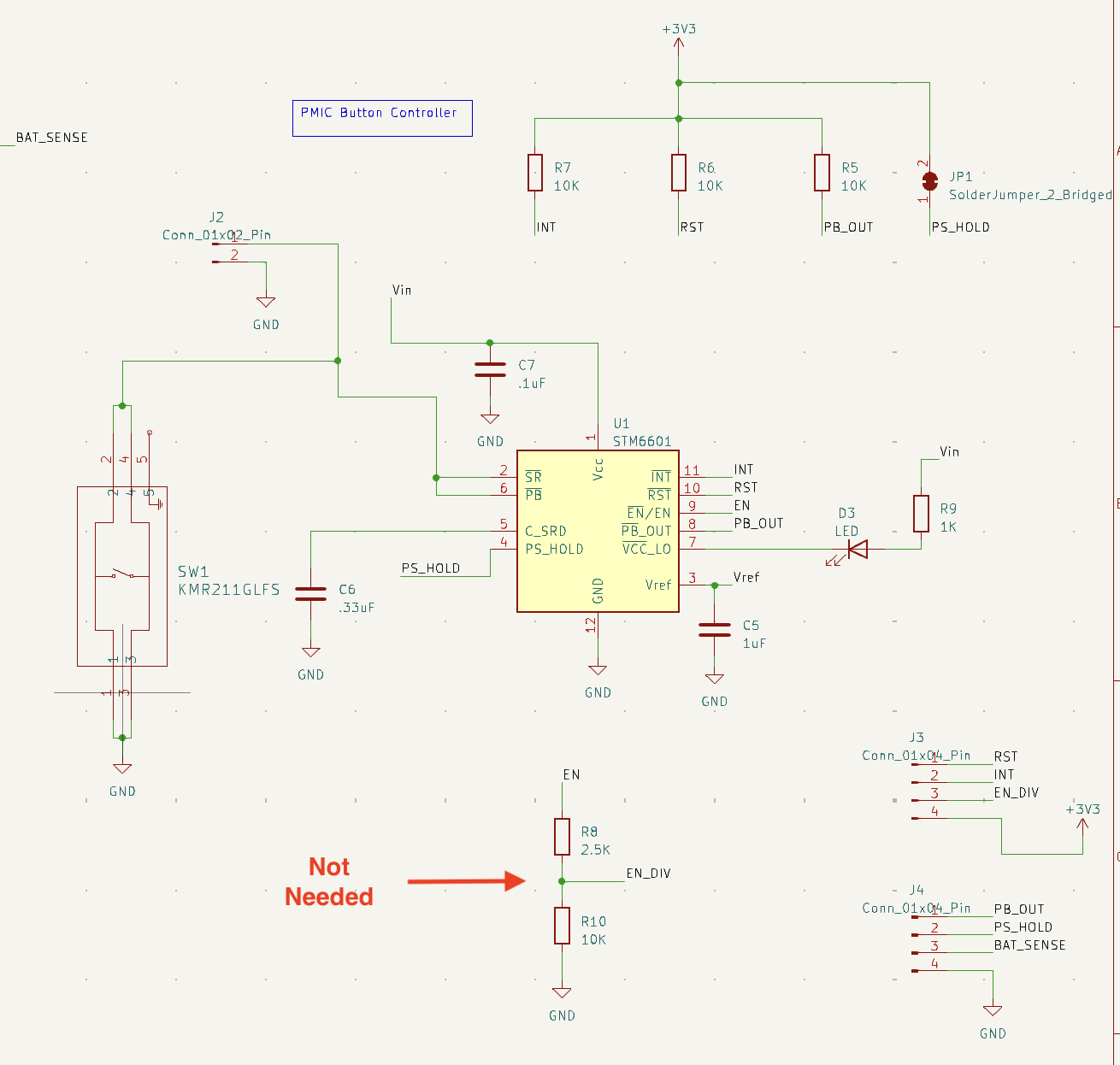
I had one last design flaw to deal with. The output voltage of the STM6601 enable pin is determined by the input voltage which can range from 3.0 – 5V depending on battery levels and if using the 5V micro-USB port. For some reason, I thought the voltage regulator enable input could only handle up to 3.3V so created a voltage divider to step down the STM6601 enable output to a safe range. This was totally unnecessary since the voltage regulator uses CMOS logic and the voltage reference is the same as the STM6601 input voltage. I just left the divider unpopulated and solder bridged the top side.
Thanks for reading! If you would like to support me and this project, please consider buying me a coffee! Every little donation help! Also subscribe to my newsletter below! It’s for curious minds, makers and anyone who shares a love of electronics.
If you found this content interesting or useful, buy me a coffee!
Bitcoin Wallet:
bc1q0vkx34w5y4yt5nq38a4rvk7gvgnxm2xv5lvyft