Some time ago, I started seriously tossing around the idea of building my own electric motorcycle. The reality of my one bedroom Seattle apartment, the time commitment and the costs of the battery alone all set in and I realized I might have to put this project on hold. But while pondering the build, I found myself most excited at the prospect of creating my own digital instrument cluster / speedometer. Even with commercial EVs, I have always loved the idea of customizable dashboards, over the air updates and all the cool features a software defined vehicle brings. So I decided to limit my ambitions and set out to build “the smart watch of motorcycle speedometers”. Taking inspiration from this blog post, I wanted to create a motorcycle display cluster that was sleek, simple and elegant.
To me, this meant it HAD to have a circular display. I had not (and still have not) seen a single fully digital, high resolution circular motorcycle speedometer. Every after market digital gauge looks like it was designed for dirt bikes or is crammed with so much information, it’s overwhelming. My gauge would have a basic UI, be fully customizable like a smart watch and would be able to interact with any age of bike.
I have finished my phase one proof of concept and am sharing all the juicy technical details here. Here is my phase one update to the DIY digital speedometer project.
Phase One Proof of Concept
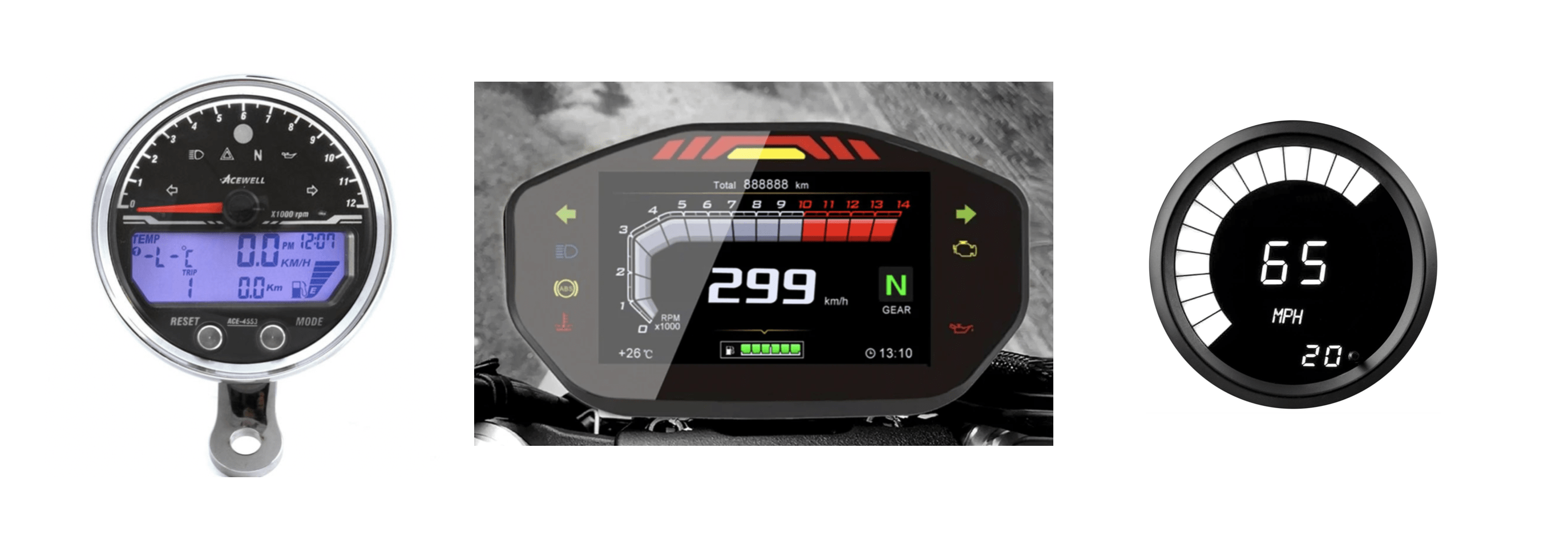
Existing after market gauges
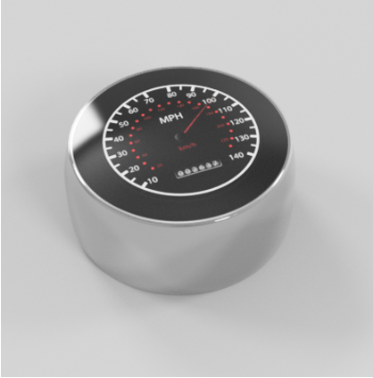
Render of project concept
Project Goals
Phase One – Proof of Concept:
- Vet out hardware / firmware architecture
- Create sleek analog gauge face
- Measure and report real speed from magnetic speed sensor
Phase 2 – Circular LCD Integration
- Move to circular TFT display
- Run off battery
- Move toward real vehicle testing
Phase 3 – Custom Hardware
- Create custom circular PCBs for form factor integration
- Create 3D printed housing for electronics
- Complete testing on real vehicle with form factor hardware
Phase 4 – Stretch Goals:
- App that connects over bluetooth where you can customize the gauge face, get trip stats and see vehicle status
- Read engine RPMs, temperature, fuel and oil status, etc.
- Different modes for music streaming and maps displays
Architecture
Single Board Computer:
After lots of research on TFT LCDs and various displays, I decided to use a single board computer instead of a microcontroller alone. Although I found some STM32 microcontrollers that had special graphics accelerators for working with LCDs, using a single board computer made the most sense to me for limited production type of projects. The cost of the part is higher but having the graphics drivers, bluetooth / network stacks already build into the linux kernel seemed like a no brainer. On top of this, I liked the idea of being able to easily port the code to any linux build and not being tied down to one specific piece of hardware.
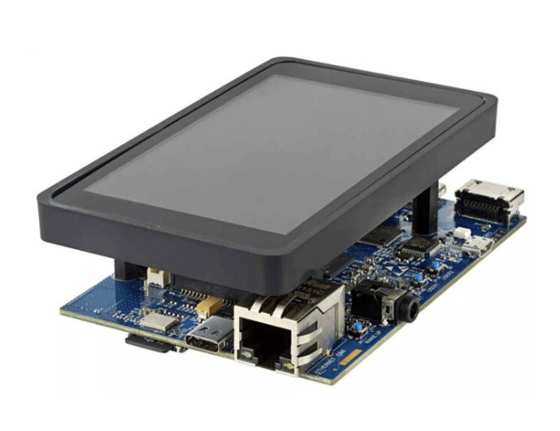
After researching a few different single board computers, I ended up choosing the STM32MP1 over the Raspberry Pi or NXP imx8. At the time, I thought I needed an ultra fast refresh rate so decided to use MIPI DSI as the display interface which is used in cell phones and high bandwidth applications. I chose the STM32MP1 since it had MIPI support, seemed to have decent documentation and had an M4 co-processor that I could use to read in all my real time sensor data to pass to the linux side. The Raspberry Pi has a MIPI DSI interface but it seems to be proprietary and they only sell a couple displays that work with it. Since the start of this project, I have seen a new round display that supports Raspberry Pi out of the box. I might have chosen this display / Pi combo if I were starting the project over again. The STM32MP157f-DK2 development kit came with a rectangular MIPI DSI display that I could use for the proof of concept development since it was set up and working out of the box.
Display:
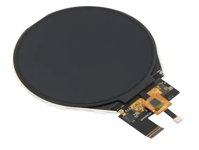
Originally, I was planning on using a 3.4″ (8.6cm) 800 X 800 resolution circular display that required MIPI DSI. It is a “true color” display with a color depth of 16.7M. This just means it can create 16.7M different shades of color using a 24 bit pixel RAM (2^24). I also wanted to run the display at 60Hz since this is the minimum refresh rate that is not noticeable to the human eye. With help from this article, I calculated the display bandwidth needed:
(resolution * pixel Ram) * (frame rate) = bandwidth
From this equation, my required display bandwidth was:
800 * 800 = 640,000
640,000 * 24 bits = 15.36Mb
15.36Mb * 60Hz = .9216Gb/sec
There are a few different display interfaces but only a couple can reach these high of bandwidths. The most common display interfaces are SPI, I2C, RGB and MIPI DSI. I2C and SPI are too slow with a max bandwidth around 1MB/sec and 10MB/sec respectively. RGB and MIPI have a max bandwidth of about 1.2GB/sec and 6GB/sec respectively. I decided to go with MIPI DSI since RGB seemed right on the edge of my requirements and most larger circular displays seemed to use MIPI DSI.
Originally, I was planning on using this display but I did not realize the STM32MP1 only supports 2 lane MIPI DSI, not 3 lane like the display requires. But I think this is for the best as the drivers were not well documented and it would have been a huge pain in the a** trying to get this display working with embedded Linux. Going forward into phase two of this project I will probably try to find a smaller RGB circular display with better documentation.
Speed Sensor:
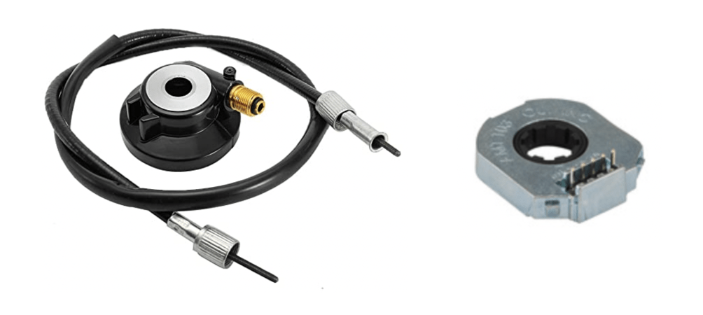
I debated what type of speed sensor to use for a while. Modern bikes mostly use CAN bus for all the communications so I did some research into what it would take to read speed values off the CAN bus. But I wanted my speedometer to work with any bike new or old so I decided to first implement the speedometer for older bikes while leaving the option to use CAN in future updates. On top of this, I did not want to have to reverse engineer every bike manufactures CAN protocols one at a time. This left me with two types of speed sensors to choose from, the stock analog speed sensor seen on older bikes or an aftermarket magnetic speed sensor. The old “analog” speed sensors literally have a small square chord like “gear” running through the cable that attaches to the wheel hub which spins the square gear based on wheel speed. Then this spinning squared gear is attached to the speedometer where it’s translated to wheel speed mechanically. I tossed around the idea of using a rotary encoder like the ones used to measure motor speed to interface with this analog cable but ultimately decided against it due to the mechanical design complexities it would introduce. I still really like this idea but it just didn’t seem practical.
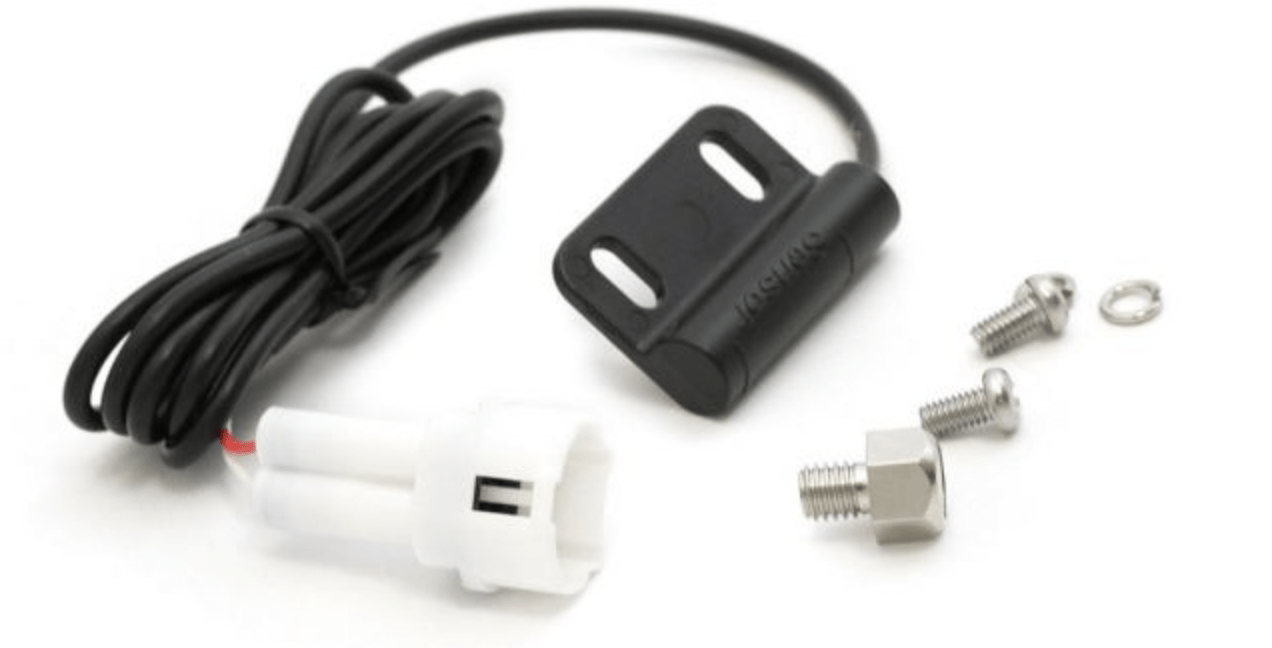
So I decided to use a magnetic speed sensor like the ones that come with most cheap after market speedometer gauges. I found this cheap sensor from a website I like called Dime City Cycles. I believe it just contains a simple read switch inside. The only downside to choosing the magnetic speed sensor is the inaccuracy at lower speeds. If you are only using one magnet, you get very low resolution at lower speeds since your speed sensor is only going to detect one “pulse” every full rotation of your tire. This corresponds to inaccurate speed measurement and choppy display updates. I will probably try to use 2 – 4 magnets when I go to actually test the speedometer on a real motorcycle. Even then, I’m nervous about the accuracy and am not exactly sure how all the after market gauges handle this. They could be taking in the engine RPMS or other data and extrapolating at these low speeds or maybe I’m just overthinking things.
Speed Sensing Circuit:
Now that I had my speed sensor picked out, I needed to design a circuit for reading the speed sensor input into the microcontroller. The circuit I chose is very simple and uses a Schmitt Trigger to read the signal in and clean up any noise. Schmitt Triggers latch an input signal to high or low based on a switching threshold in order to reject any noise on an input signal.
If you’re interested in electronics, Schmitt Triggers are a must have in the “toolbox”. And lucky for you, I have a very detailed post on exactly how they work! Check out my post on Schmitt Triggers!
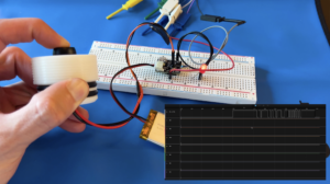
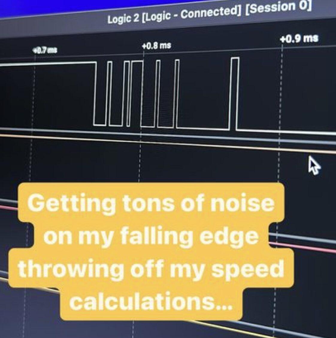
At first I thought that using a Schmitt Trigger would provide a perfectly clean input signal with no noise but I forgot about switch bouncing. Switch bouncing is something that occurs on the output signal of a switch or button where the signal bounces between “on” and “off” a few times due to the mechanical nature of the switch. When I first started testing the speed sensor I saw that I was reading in a bunch of extra falling edges and after hooking up a logic analyzer, determined that it was due to switch bouncing. I thought about adding a low pass filter to the circuit to clean up any unwanted high frequency switching but decided to filter this in software instead.
For the Schmitt Trigger, I ended up picking a TI Inverting Schmitt Trigger buffer IC to use in the speed sensing circuit. This IC has a fixed high / low switching thresholds which is based on the input voltage. I’m using an input voltage of 3.3V so the low switching threshold is set to 2.2V and the high switching threshold is set to 2.9V.
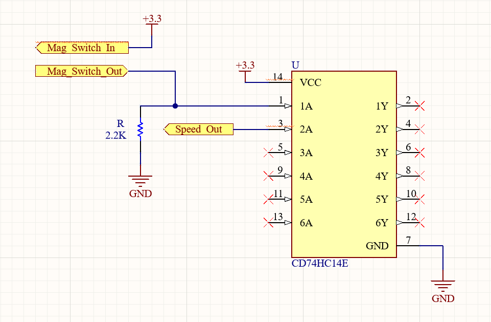
When the magnet spins by the sensor, it closes the internal reed switch which connects the Mag_Switch_In to the Mag_Switch_Out and feeds the 3.3V signal into the Schmitt Trigger IC. From there the Schmitt Trigger inverts the signal and outputs a high or low on the Speed_Out which is fed into the microcontroller GPIO input. The 2.2K resistor acts as a pulldown so that the input to the Schmitt Trigger is never left floating.
Creating the Gauge Display
STM32MP1 Image:
ST had an example Yocto image for using the STM32MP1 with Qt. Qt is a cross platform software for creating various types of UI. It was the perfect choice for this project since it is fairly easy to use, has simple design UIs and can be intertwined with C++. On top of this, it’s cross platform so it can be used with all flavors of Linux, Windows, Mac and almost anything else you can think of.
This was the first time I have worked with Yocto and the learning curve is steeeeep. Yocto is a tool that allows you to create custom linux distributions for embedded targets. The Qt example image provided by ST is not officially supported by them and there were some bugs / issues to work through. I spent many hours tweaking things, removing trouble libraries and configuring my linux VM to be able to build the image. Running on a VM with limited memory, it took almost 15 hours to build the image…
Once I got everything build and linux booting, I set up Qt Creator, the default Qt IDE, for cross compilation. So now I could create Qt projects on my regular computer and compile them to run on the STM32MP1 device. From there, I could start to build out the UI to my speedometer as well as gauge faces.
If you’re interested in learning more about how I set up Yocto, built the image or set up Qt Creator for cross compilation, check out my post, How to Setup STM32MP1 with Qt!
Qt:
I chose Qt because of it’s easy to use design tools and ability to load in existing images. I didn’t want to manually code up the graphics of my display using something like OpenGL because I don’t think I’d ever be able to get the sleek designs I was looking for without investing tons of hours. Qt gave me the ability to load in professional looking stock photos with no graphics coding required.
I searched through Adobe Stock and found an analog gauge photo that I liked. I wanted to start with an analog gauge face for the digital speedometer in order to show the versatility of the project. You could have the digital gauge look futuristic, or like an old classic speedometer. I then used PhotoShop to deconstruct the gauge photo. I pulled out the needle from the gauge face to treat them as separate layers and erased the trip and odometer numbers. Below is a picture of each gauge “layer” after the PhotoShop magic.
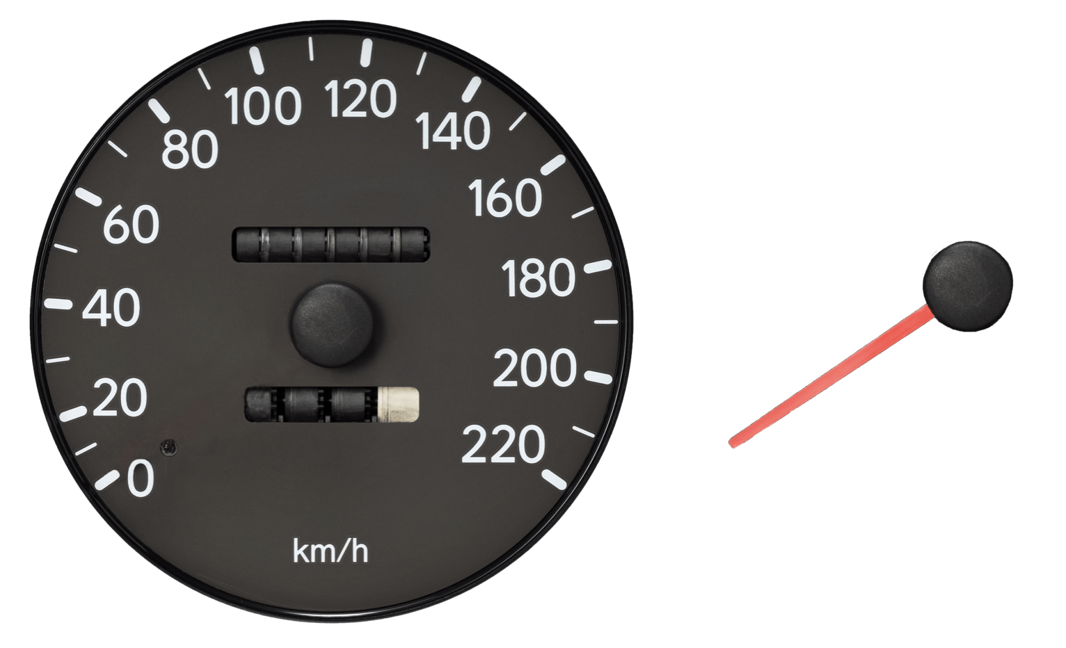
I could now overlay these two images within Qt Creator in order to control each face independently. I anchored the needle layer onto the center of the gauge which allowed me to call a rotate function and create the needle animation.
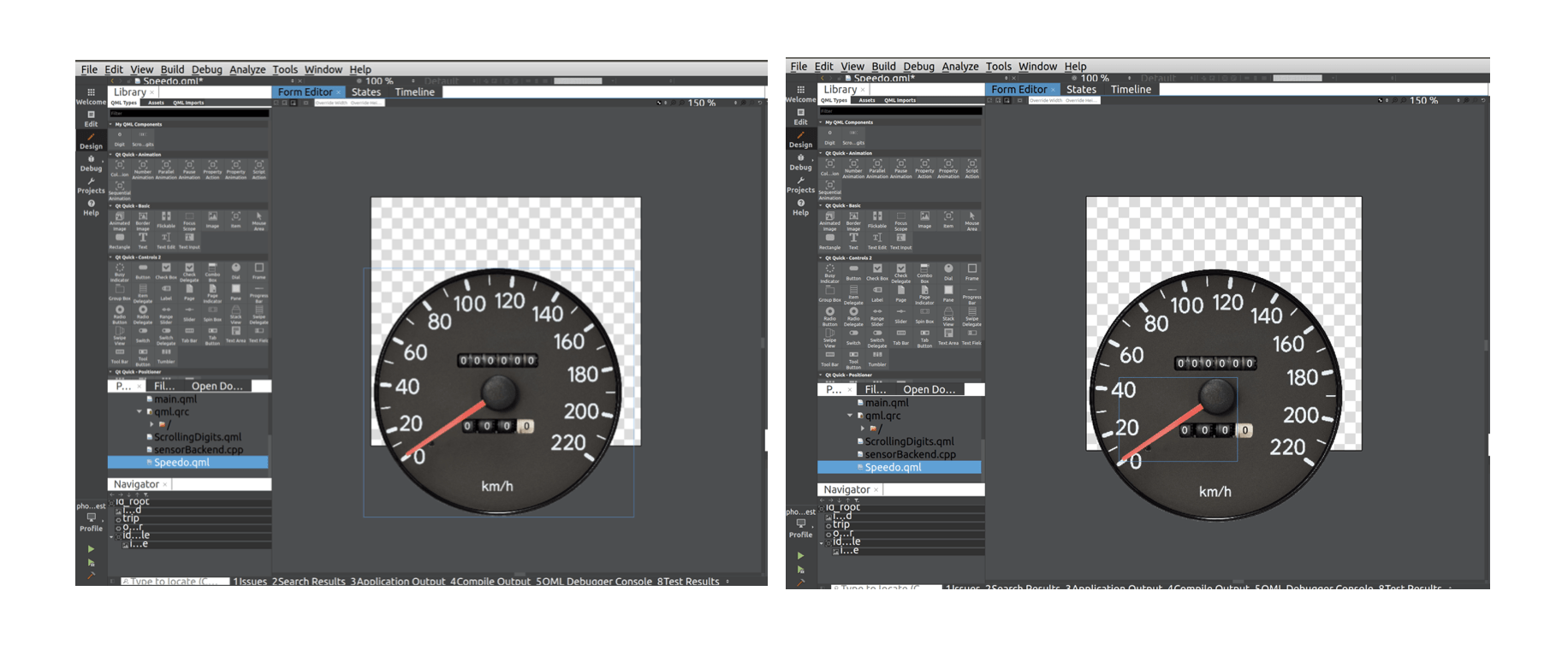
I found a Qt scrolling digits example online which I modified to fit my needs for the trip and odometer animations. And after some finagling with rotation smoothing, changing the last scrolling digit from white to black and mapping the needle rotation from angle to speed values, my gauge display was finished. Qt saved me so much time creating this display.
Once the display itself was finished, I tied in a C++ “backend” that would handle passing real data to the display. I found an example project for the STM32MP1 M4 co-processor that could pass messages between the M4 core and the A7 Linux core using a virtual UART or Inter Processor Communication (IPC). I figured out how to set up a serial port in Qt and assigned it to the virtual UART. When new messages come in from the co-processor, Qt reads them in and unpacks the received bytes into float values before notifying the display application of new data. Qt uses a signal / slot architecture for event handling. When a particular event occurs, a “signal” is emitted and an associated “slot” function is called to handle the incoming signal. When new speed data is received, a signal is emitted which calls a slot that handles updating the display. How the M4 co-processor firmware actually calculates speed is another discussion.
M4 Firmware
The firmware for this project was all developed on the M4 co-processor in C / C++. I decided to use the co-processor to read in the speed sensor and send all the sensor data to the embedded Linux side. This task was pretty time critical and I did not want to use Linux for this. The co-processor packages up speed and odometer data and sends it to the A7 Linux chip over the “Inter processor Communications” (IPC) virtual UART. Once the Linux side receives these messages, the Qt application is notified of new values and the display is updated automatically.
Initially, I set up the firmware to trigger an interrupt on every falling edge of the speed sensor signal. I had a timer interrupt trigger at a 50Hz intervals and would then check how many falling edges were detected in that period. These falling edges would correspond to how many rotations of the wheel had occurred (since I am currently only using one magnet) which can be converted into a distance since we know the circumference of the wheel. At that point, we know the distance traveled and how much time has passed (50Hz = 20mS period) so we could calculate the speed. But due to the switch bouncing issues we discussed in the “Speed Sensing Circuit” section, the firmware was reading in multiple falling edges every time the speed sensor signal transitioned high to low. This threw off the speed calculation and I had to implement some sort of de-bouncing in firmware.
To de-bounce the speed sensor I decided to poll it instead of using interrupts. Here’s how it works: If I see the speed sensor signal transition from high to low (go from 1 -> 0), I make sure it stays low for 3 readings in a row before calling it a valid transition. The three readings in a row ensure that any bouncing that was occurring has stabilized and that I only read in one real transition. I just had to determine how fast I needed to be polling the incoming signal. Choosing the max speed of my speedometer to be 220KPH (~140 MPH), at that speed I should get 1 sensor transition every 4.9mS.
I chose to poll the speed sensor signal 15 times faster than that worst case “tick time” of 4.9ms which gave me a polling frequency of 3KHz. So that means I am checking the sensor input signal 3,000 times a second. And I need to see 3 valid transitions in a row at that high speed polling frequency in order to know my signal had undergone a real transition. That means the sensor signal needs to hold a transition for at least .98ms to be considered “real”. This polling update seemed to fix the switch bouncing issues nicely!
Now lets get into a little more detail on the actual speed calculation. We are now tracking the magnet successfully so we know how many times the magnet is spinning past the sensor. We’ll call these “ticks”. As I stated above, we are calculating speed using a timer interrupt to track how long has past and looking at the amount of ticks to determine the distance traveled. There is one small problem with this method, we need to track overflow cases where the timer interrupt triggers but the wheel has not undergone a full rotation so we have no ticks yet. In these cases, we can’t calculate a new speed since we don’t know how much distance the wheel has traveled. We will increment an overflow counter and re-asses on the next timer interrupt. On the next timer interrupt, if we now see a valid tick, we now know the distance traveled and we’ll add in the overflow time to our speed = distance / time calculation.
Lastly, since most of my initial testing was at lower speeds, there was some noticeable jitter on the display. This is due to the poor resolution at lower speeds since we are only detecting full rotations with one magnet. There is only so much I can do about the jitter when using just one magnet but I had a few tricks up my sleeve. First, I increased timer interrupt that calculates speed from 50Hz to 100Hz. This helps in overflow conditions described above. Making the timer interrupt has small as possible helps minimize error in overflow conditions and in the future I will test exactly how fast I can increase this to. I also implemented a 12 point moving average filter to help clean up the jitter and smooth out the display animation. This just averages the last 12 speeds together in order to ensure we don’t have big step changes in speed.
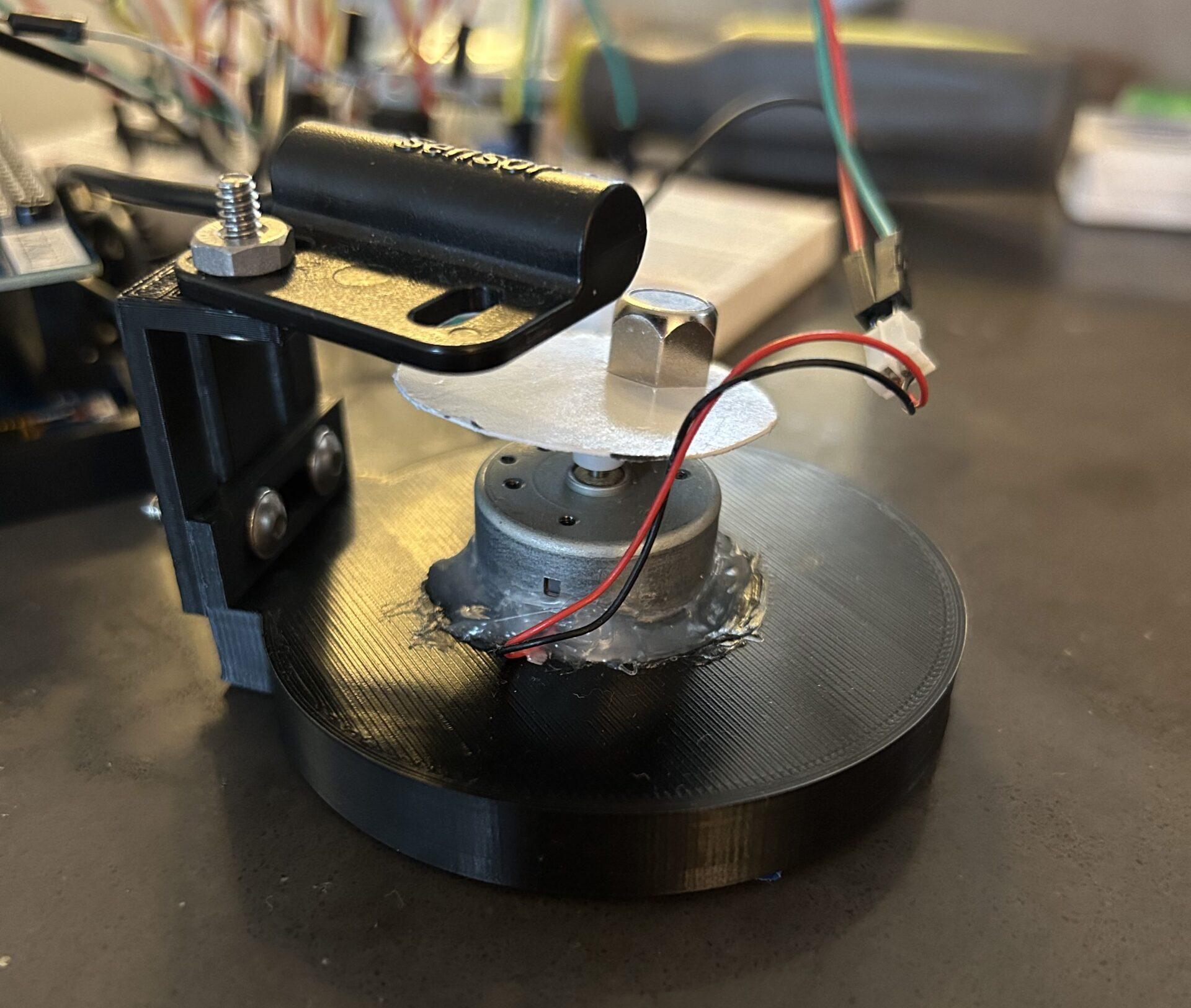
Integration
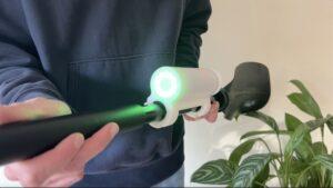
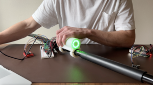
Once I had a the speedometer display working and the core of my firmware written, it was time to start testing. I just had one problem… I don’t actually own a motorcycle. In order to test I dug through my spare parts bin and found a little brushed DC motor. I hot glued a disk with a magnet onto the shaft and 3D printed up a make shift test stand. The test stand holds the motor in place and uses a printed L bracket to mount the speed sensor over the spinning magnet. This way I could test on a “real” speed input.
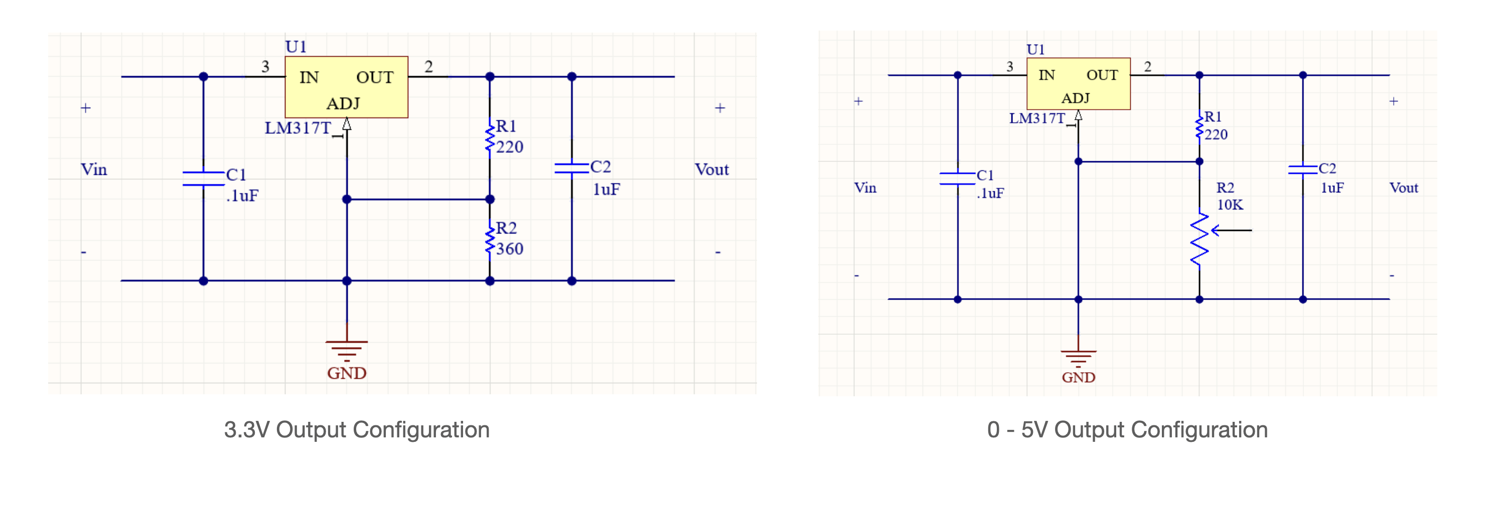
With my new test stand printed, I needed the motor to actually spin. I needed 3.3V for the Schmitt Trigger circuit and an adjustable voltage for the test motor. I found a couple LM317 linear regulators in the spare parts bin and threw together a couple circuits to produce 3.3V and an adjustable voltage. I decided to drive the motor from 0V – 5V so I grabbed a potentiometer in order to control my voltage range manually.
This motor voltage range only gives me a max RPM of about 2,000 to test with. This is fine for my initial phase one tests but didn’t allow me to test a whole lot of speed ranges.
With this test setup, I was able to work through many of the firmware issues described in the previous section and ultimately get through this first phase of development!
Next Steps
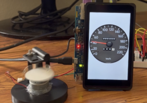
Phase one of this project is now complete! I was able to accurately read in a real speed from the sensor and display it to a professional looking display.
The next phase of this project will be customizing some of the hardware. First, I am going to figure out how to incorporate a circular display. This is one of the key goals of the project and I really want to see this thing with a full circular TFT display! I am also planning to implement at least one other gauge face to show the versatility of the design. I will probably choose a more digital looking display to contrast the analog display I currently have. If both of these go well then I may move into phase three of the project which is to fully design my own custom circular PCB. I would love to design a custom PCB where I can mount everything into a low profile round housing and stick it on a real motorcycle.
Thanks for reading!
If you found this content interesting or useful, buy me a coffee!
Bitcoin Wallet:
bc1q0vkx34w5y4yt5nq38a4rvk7gvgnxm2xv5lvyft