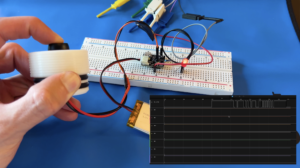
A Schmitt Trigger is a very practical circuit that helps eliminate switching noise on an input signal by implementing what is called hysteresis. Imagine you have a system that feeds a 0 – 5V signal into a rising/falling edge GPIO interrupt. With no Schmitt Trigger, the interrupt would trigger anytime the signal rises or falls above or below 3.3V. If there is noise on the signal this could cause multiple invalid interrupts to fire as the signal transitions low to high or high to low. The hysteresis of a Schmitt Trigger sets the switching point as a range instead of a constant midpoint. So in our example, instead of triggering an interrupt anytime the signal rises or falls above or below 3.3V, the signal has to rise above say 4V in order to be considered “on” and fall back below 2.5V in order to be considered “off”. This gives you much more margin to resist any noise on input signals. We will go into more detail on how this works and what hysteresis is but in order to really answer the question, “How do Schmitt Trigger Circuits Work?” we first need to go back to some op amp basics.
Comparators
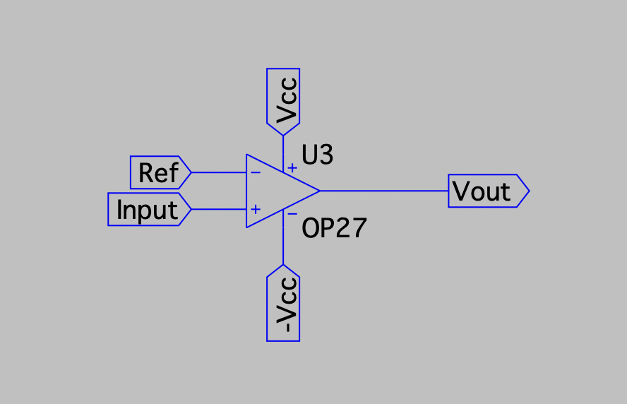
At their core, Schmitt triggers are comparators. The comparator is one of the most basic op amp circuits outside of the voltage follower buffer. A comparator takes a reference voltage into it’s inverting input and takes another signal into it’s non-inverting input. It then compares the input signal to the reference voltage and output’s Vcc if the signal is higher than the reference or -Vcc if it’s lower. In order to truly understand Schmitt Triggers, first we need to discuss how the comparator circuit works.
Differential Gain
In it’s most basic state, with no positive or negative feedback (open loop), an operational amplifier is a differential amplifier with an ideal gain of infinity (in reality just a very very large gain ~100,000). This is one of the three golden op amp rules, “op amps have infinite open loop gain”. The differential gain of an op amp can be defined as:
Where A is the op amp gain which, as we discussed above is very large, V+ is the non-inverting input voltage and V- is the inverting input voltage. From this equation, we can see how the comparator works. When the input voltage (V+) is larger than the reference voltage (V-), we get Vout = A * (positive value) = Vcc and when the input voltage (V+) is less than the reference voltage (V-) we get, Vout = A * (negative value) = -Vcc.
Feedback
On last important concept to review before discussing Schmitt Triggers is feedback. In op amp circuits, there are two types of feedback used, negative and positive. Negative feedback is much more common for a few reasons we’ll discuss.
Negative Feedback
Negative feedback is where the op amp output is fed back to the inverting input pin. This creates stability with op amps and acts to “tame” the extremely high open loop gain. The easiest way to think about negative feedback is the output is fed back so that the non-inverting and inverting input pins try to sit at the same voltage potential. This is another of the golden rules of op amps when using negative feedback, “the potential difference between the input pins is zero”. We can demonstrate this effect using the differential gain equation above and a simple example of a voltage follower buffer.
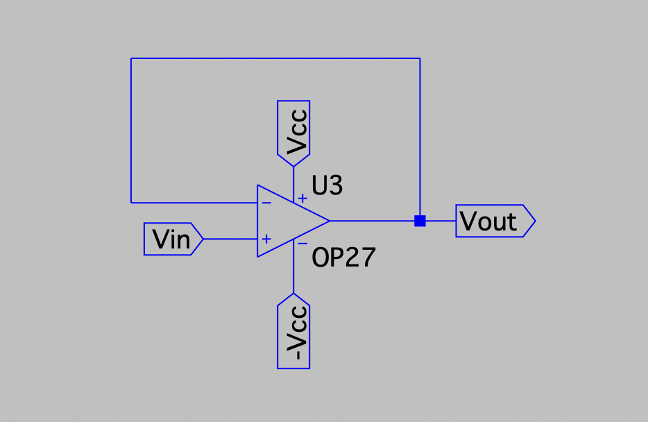
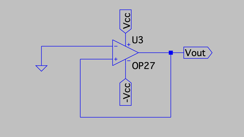
The voltage follower is a very simple circuit that has negative feedback straight from the output of the op amp to the inverting input pin. From this circuit we can modify our differential gain equation to:
which can simplify to:
From this equation, we can see how negative feedback works. Vout which is fed back to the inverting input will be a tiny fraction smaller than the non-inverting input voltage. This tiny difference is just enough to keep the huge open loop gain under control and keep the inverting / non-inverting inputs essentially equal to each other. In the above example, let’s pick some values to demonstrate this. Say V+ is 5V and A is 100,000. This would give us a Vout or V- of 4.99995V. The tiny difference between the inverting and non inverting input would be multiplied by 100,000 and is just small enough to keep the gain / Vout under control.
There are lots of great articles going further into detail on the applications of negative feedback but in the context of Schmitt Triggers, we are actually more interested in positive feedback.
Positive Feedback
Positive feedback is less useful than negative feedback and there are only a couple practical applications for it. One is oscillators and another is Schmitt Triggers. Positive feedback creates a “bi-stable” output. This means that when positive feedback is connected, the output of the circuit can only be Vcc or -Vcc. To demonstrate this, once again we’ll look at the differential gain equation. For simplicity let’s look at the configuration where we have positive feedback from the output to the non-inverting input and the inverting input is grounded.
In this configuration we can simplify our differential gain equation to the following:
Here we can see that if Vout starts out negative, the op amp would saturate to -Vcc and if Vout starts out positive then the op amp would saturate to Vcc.
Schmitt Triggers
Finally, we have enough background information to answer the question “how do Schmitt Trigger circuits work?”. Well actually, let’s review the three golden op amp rules that will help us analyze the Schmitt Trigger circuit.
- Op amps have infinite open loop gain
- The potential difference between the inverting and non-inverting inputs is zero.
- No current flows into either input
Okay, now we are really ready to talk Schmitt Triggers. Schmitt Triggers utilize positive feedback to saturate the op amp to either Vcc or -Vcc but implement this positive feedback in a clever way. Once again, a Schmitt Trigger is just a comparator where the reference voltage is not a constant value but changes based on the output voltage. This is called hysteresis and gives a much wider range for the switching point which helps reject signal noise. Think of a Schmitt Trigger as a comparator where the reference voltage is just a fraction of the output voltage.
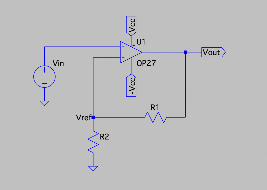
As you can see from the schematic, the positive feedback is implemented as a voltage divider. This means that the voltage on the non-inverting input will be a fraction of the output voltage. Because of this and the fact that Vout will always be Vcc or -Vcc (positive feedback always creates bi-stability as discussed above), we can pick values of R1 and R2 to set the “reference” of the “comparator”.
Analyzing the circuit using the golden op amp rules we get the following equation for the non-inverting input voltage:
Which can be simplified to:
Since this is a positive feedback configuration, we know that the output will be bi-stable. So we can set Vout to Vcc and -Vcc and solve for the value or Vref.
Vout = Vcc:
Vout = -Vcc:
From these equations we can see how a Schmitt Trigger works. Let’s pick some actual values to better demonstrate the operation. Let’s say the op amp rails (Vcc / -Vcc) are set to +/-12V and we have an input signal that swings between +/-5V. If we want the output to switch at -2.5V and +2.5V, we can select R1 = 5K Ohms and R2 = 19K Ohms. Now when the input signal rises above 2.5V, the output will switch to 12V and when the input signals falls below -2.5V, the output will switch to -12V.
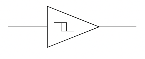
This is where the Schmitt Trigger symbol comes from. The symbol represents the switching range when an input signal is transitioning from high to low and low to high.
Non-Symmetrical Schmitt Trigger
While the above circuit is useful for AC signals with a positive and negative component, often times our input signal only has a positive component. This is where the non-symmetrical Schmitt Trigger comes in handy. Say we have an input signal from 0V – 5V and would like to apply a Schmitt Trigger to it. We’ll demonstrate this using an inverting Schmitt Trigger with a single supply meaning the positive rail of the op amp will be connected to Vcc and the negative rail will just be grounded. Also, to simplify our calculations we will set Vref = Vcc = 5V.
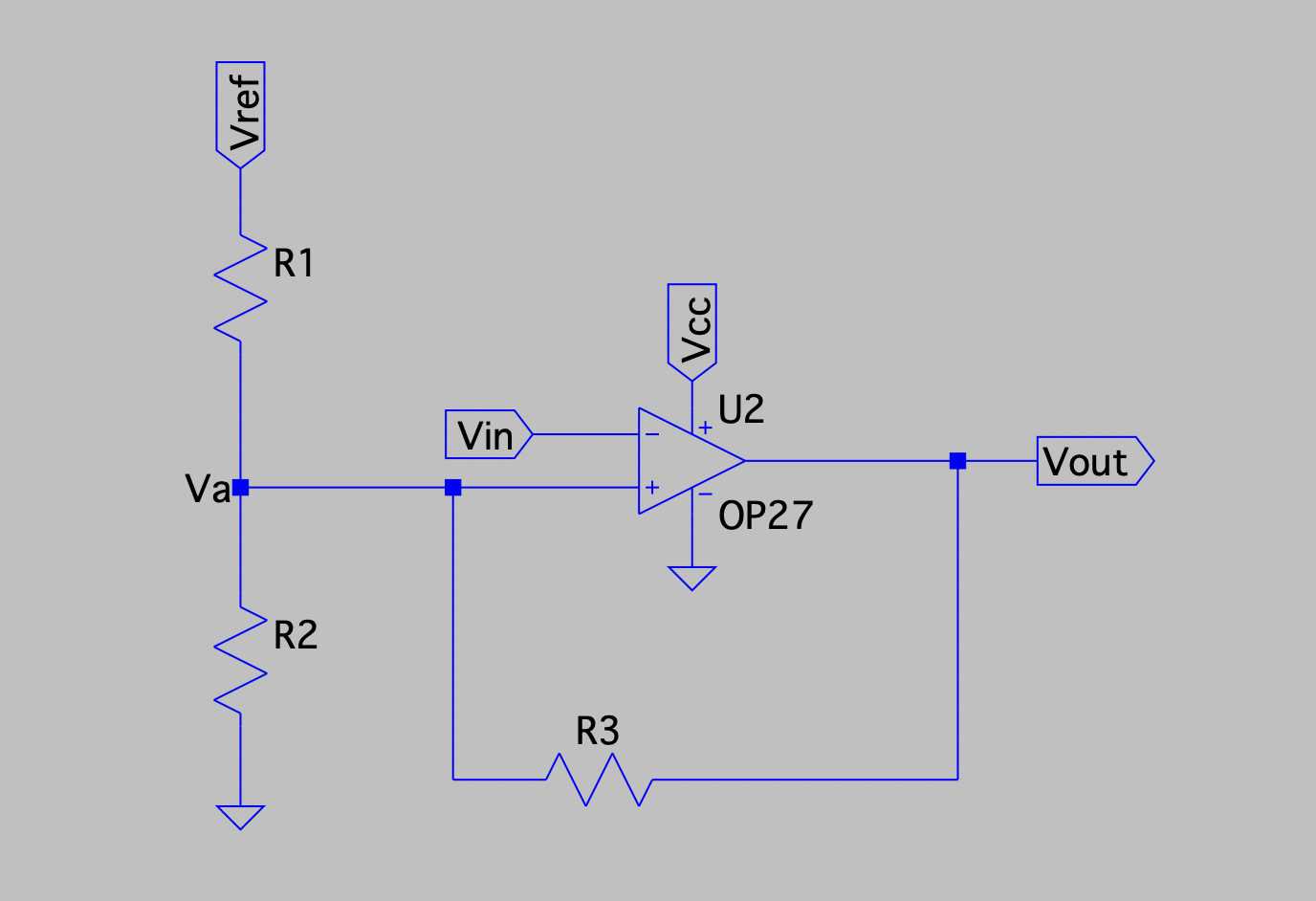
Since this is an inverting Schmitt Trigger, the logic will be flipped. When the input signal rises above the positive threshold, the output will latch to 0V and when the input signal falls below the negative threshold, the output will latch to 5V. In order to calculate the positive / negative switching thresholds, we need to find the voltage at the non-inverting input, Va, for all output conditions.
In the case where the output voltage is at 0V, our resistor network can be simplified as follows:
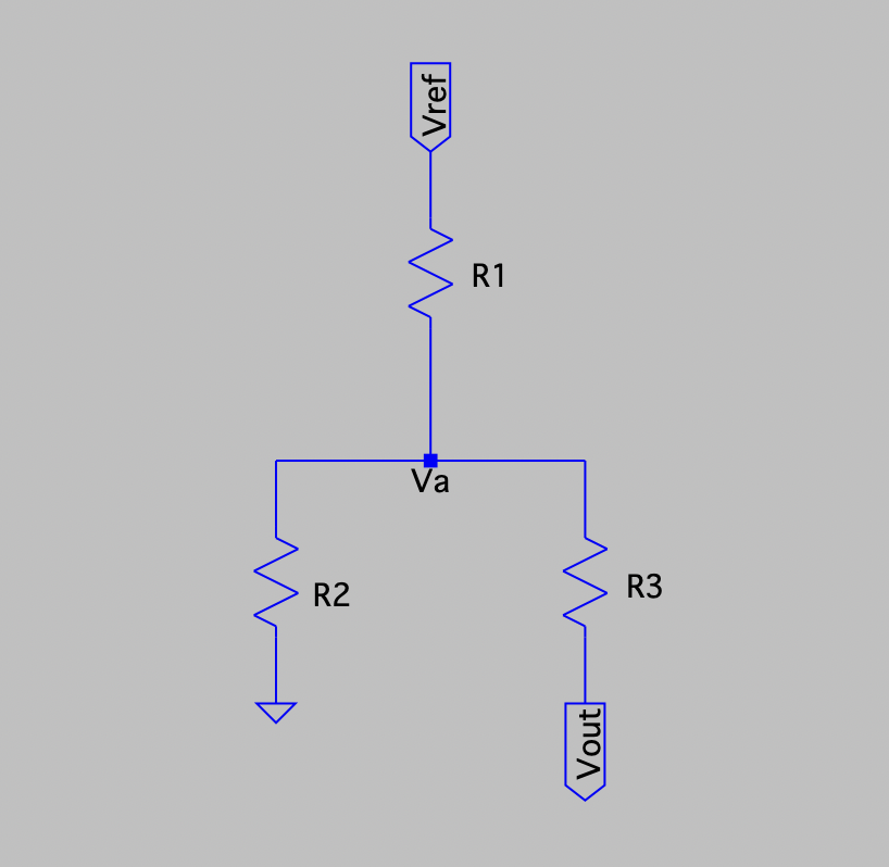
Since Vout is equal to 0V or GND, this is just a voltage divider where one leg is R1 and the other leg is R2 || R3. The voltage at the non-inverting input, Va, can be defined as:
In the case where the output voltage is at Vcc = 5V, our resistor network can be simplified as follows:
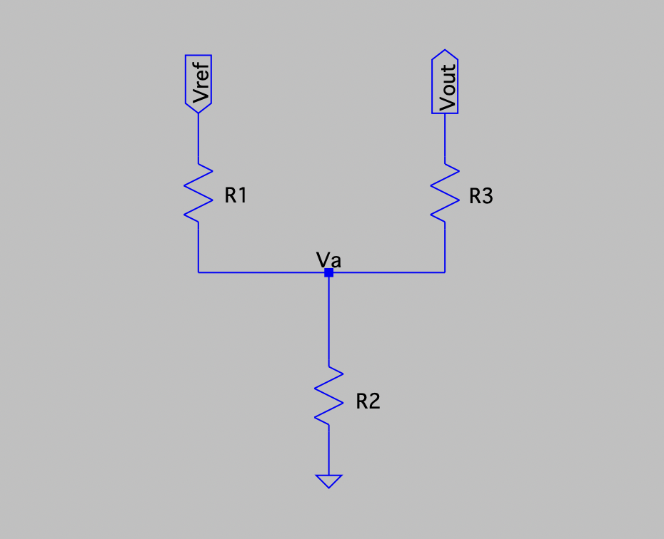
This is just another voltage divider where one leg is R1 || R3 and the other leg is R2. The voltage at the non-inverting input, Va, can be defined as:
Using our example inputting 5V for Vcc and setting all three resistor values to 5K Ohm, we can see that the high switching threshold is given by:
And the low switching threshold is given by:
This means that the output voltage would swing low when the input signal rises above 3.333V and would swing high when the input signal falls below 1.666V.
Going Further:
Although Schmitt Triggers can be made with op amps as shown, there are specialized ICs that are made for these applications. Electronics Hub has a great walk through of a transistor based Schmitt Trigger design. But if you are designing a circuit in need of a Schmitt Trigger in practice, I would recommend using one of these specialized ICs that are very low cost. There are tons of different ICs with various high / low switch thresholds. Just get on Digikey and do a quick filter of whatever high / low switching thresholds you need!
If you want to see an example of Schmitt Triggers used in a real life application, check out my diy speedometer project!
Hope you found this explanation of how Schmitt Trigger circuits insightful!
If you found this content interesting or useful, buy me a coffee!
Bitcoin Wallet:
bc1q0vkx34w5y4yt5nq38a4rvk7gvgnxm2xv5lvyft