Although UARTs (Universal Asynchronous Receiver Transmitter) are one of the easiest ways to communicate with a microcontroller, there are many incompatible standards, converters and cables to figure out. Sorting through all of this as a new engineer can be overwhelming. This post will teach you everything you need to know about UART vs RS232 and how to interface with Microcontrollers over UART. This is the ultimate guide to microcontroller UART communication.
UARTs:
Basics
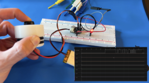
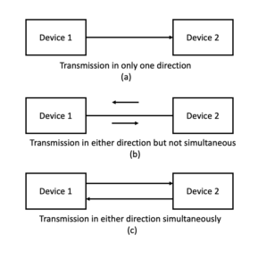
A UART or Universal Asynchronous Receiver Transmitter, is a hardware module that allows for serial communication between devices. Serial communication is a stream of bits that are transmitted or received on a single wire, one bit at a time. The figure below shows the three different configurations UARTs can have. Simplex (a) is defined as fixed, unidirectional data transmission. Half duplex (b) means non-simultaneous, bi-directional data transmission and full duplex (c) means simultaneous, bi-directional data transmission. While a simplex and half duplex setups only need one wire, full duplex requires two.
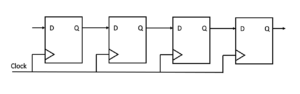
The Asynchronous aspect of UART has to do with clocking. UARTs do not require a clock signal while more complicated protocols such as SPI (Serial Peripheral Interface) or I2C (Inter-Integrated Circuit) do. At their core, UARTs are implemented as shift registers which shift a bitstream in or out one bit at a time. This can be thought of as a cascade of D flip-flops where each system clock cycle shifts the next bit out of the last stage output.
I know I just said that UARTs do not require a clock signal, so why is a clock signal used to shift bits out of the UART shift register? Well let me emphasize that UARTs do not require shared clock signal between the two devices. But each individual UART still relies on a clock signal from its internal system. Both devices share a common data speed called baud rate which ensures data transmission completes successfully.
Baud Rate
Since both devices share the same baud rate, no clock signal needs to be shared between devices. Baud rate is defined as the speed at which data is transmitted or received over a UART in bits per second. Since each device knows the timing of the respective incoming or outgoing data, there is no need for a shared clock signal. This allows UARTs to be implemented with less pins than other serial protocols. UARTs do have some limiting factors with data speed and transmission distance. Depending on the protocol used, maximum baud rates are in the range of 250 Kb/s (4 uS per bit) and maximum distance is about 50 feet (15 meters). In order for communication to work smoothly, the baud rates of the two devices have to be within 10 percent of each other.
This covers the basics of UART serial protocol. The University of Wisconsin Madison has a good article explaining additional concepts related to the actual data transmitted in a standard frame. To fully understand UART vs RS232, first a discussion about logic voltage levels is needed.
TTL
The majority of microcontrollers work between 0V and Vcc with Vcc being 3.3V or 5V. These voltage levels are called TTL (Transistor-Transistor Logic) representing 0V as a logic 0 and Vcc as a logic 1. UARTs that are output on a microcontroller’s pins use TTL to differentiate between a 0 or a 1 while sending or receiving data. Not all systems and standards expect TTL signals which is the root of a lot of confusion with UART vs RS232 and serial to usb converters.
RS232:
RS232 (Recommended Standard 232) is just a standard that defines what voltage levels should specify a logic 0 or logic 1 in UART serial communication. Everything we have talked about in the previous sections still applies to RS232 except the voltage levels that define a logic 0 or logic 1. Instead of using TTL, RS232 defines a logic 0 as a voltage between +3V and +15V, and logic 1 as a voltage between -3V and -25V. This is why trying to read RS232 directly out of a microcontroller will not work. These higher voltage signal levels make the protocol somewhat less susceptible to noise. Because of this, RS232 signals can communicate across a longer distance than TTL signals.
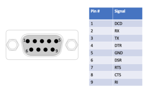
One other key feature of RS232 is the connector type. Almost all RS232 in industry use D-Subminiature (often called D-Sub for short), 9-pin connectors called DE-9 connectors. If you see a serial port going to a 9-pin D-Sub connector you can pretty much assume it is RS232. Although there are many other signals aside from Tx and Rx that are defined in the RS232 standard, most often they can be ignored.
The similarities and differences between UART vs RS232 should be clear but this is often not the only source of confusion. Most confusion around UARTs actually occurs when trying to read serial data from one device to another. There are various adapters and converters that have to be used correctly in order for successful communication.
Converters, Adapter and Dongles:
Now that the difference between UART vs RS232 is clear, the question is how to successfully interface with UARTs? In early stages of development, microcontroller are often connected to a computer serial port in order for test and debugging. When trying to connect to a serial port there are many factors that can cause issues. Aside from things like baud rates, parity bits, etc, there are many types of converter chips, serial to USB adapters and computer dongles to manage.
TTL to USB
FTDI (Future Technologies Devices International) has an extremely popular chipset, the FT232R, which acts as a UART to USB converter. This chipset converts a UART at TTL to USB protocol which can be read by your computer USB port. This is the easiest way to read serial data straight off a microcontroller into a computer. These chips are often embedded into USB to serial adapter cables which plug directly from your computer USB port to a microcontroller’s pins. This means that all you need to get started reading from a microcontroller UART is an adapter cable like this one, FTDI TTL to USB. FTDI is not the only option for converting TTL UART to USB, like this PL2303TA based converter, PL2303TA TTL to USB. But FTDI is by far the most common.
Note, if you are planning to use one of these adapter cables for Arduino re-programming, you need to ensure it has the DTR (Data Terminal Ready) signal included. Most FTDI to USB adapter cables do. Arduino uses this signals to initiate the reset and boot loader reboot sequence.
RS232 to USB
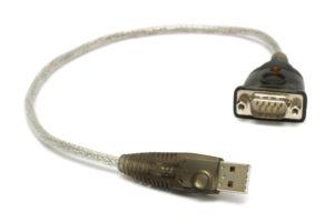
There are multiple integrated circuits that convert from TTL to RS232. The MAX232 by Maxim Integrated Products or Sipex SP3232 are two popular choices that can convert a TTL UART signal to RS232 or vise versa. These ICs relies on external capacitors in a charge pump configuration to create the positive and negative voltage needed for RS232. They can use a 3.3 or 5V input voltage so it works well with all types of Microcontrollers. If your project outputs RS232, you will need an RS232 to USB adapter cable in order to read serial data from your computer USB port. Pay attention to ensure you buy the correct male or female D-Sub connector and male or female screw terminals which fits your needs.
They also make RS232 breakout boards which converts TTL signals to RS232 output on a D-Sub connector which can be useful if you do not have access to a TTL to USB adapter cable.
If you found this content interesting or useful, buy me a coffee!
Bitcoin Wallet:
bc1q0vkx34w5y4yt5nq38a4rvk7gvgnxm2xv5lvyft